Battery pack
A technology for battery packs and battery modules, applied in the direction of batteries, battery pack components, battery caps/end caps, etc., can solve problems such as pressure rise in battery containers
- Summary
- Abstract
- Description
- Claims
- Application Information
AI Technical Summary
Problems solved by technology
Method used
Image
Examples
no. 1 Embodiment approach
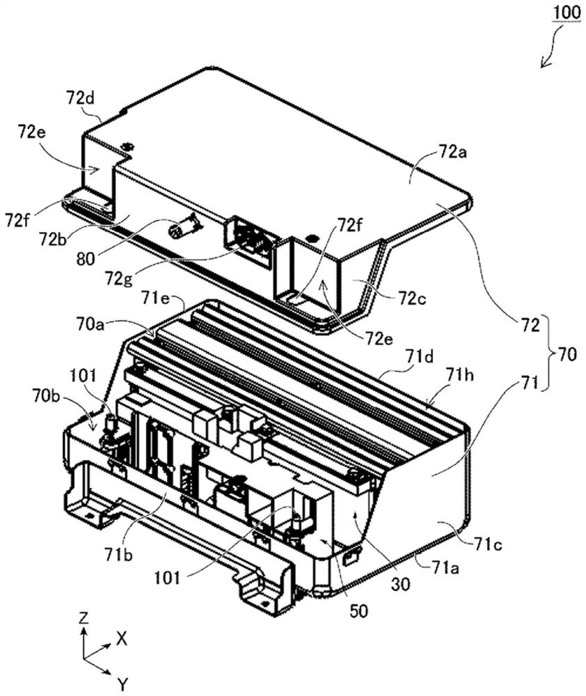
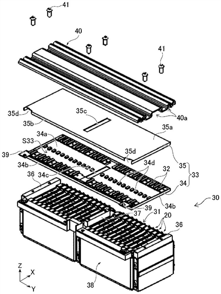
[0030] figure 1 It is an exploded perspective view of the battery pack 100 according to the first embodiment of the present invention. figure 2 It is an exploded perspective view of the battery module 30 of the battery pack 100 according to the first embodiment of the present invention.
[0031] The battery pack 100 according to the first embodiment of the present invention is installed in vehicles such as electric vehicles (EV) and hybrid electric vehicles (HEV), for example. The battery pack 100 stores electric power supplied through a pair of input / output terminals 101 described later in the battery cells 20 , and supplies the electric power stored in the battery cells 20 to electric devices such as motors of the vehicle through the input / output terminals 101 .
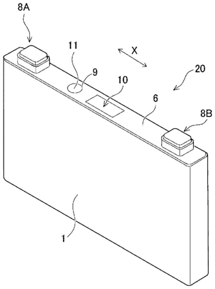
[0032] The battery pack 100 includes a battery module 30 including a plurality of battery cells 20 composed of secondary batteries, an electric unit 50 arranged at a predetermined interval from the battery module...
no. 2 Embodiment approach
[0081] In the battery pack 100 according to the second embodiment of the present invention, as Figure 8As shown, an engagement protrusion 82 for holding the edge of the filter 91 is formed along the inner peripheral surface of the duct 80 so as to span one circumference in a portion of the duct 80 on the upstream side with respect to the filter 91 . In addition, as long as the engaging protrusion 82 can hold the filter 91, it may be provided so that it may hold the filter 91 at several places (partially). The engagement protrusion 82 has a first holding surface 82a facing the edge of one surface 91a of the filter 91 and an inclined surface (neck portion) 82b extending from the inner end of the first holding surface 82a toward the inner surface of the duct 80 . The inclined surface 82b is formed such that the inner diameter decreases from the upstream side (the second storage space 70b side) to the downstream side (the side opposite to the second storage space 70b). Thereby, ...
no. 3 Embodiment approach
[0085] In the battery pack 100 according to the third embodiment of the present invention, as Figure 9 As shown, a protrusion 92 c protruding toward the first holding surface 82 a is formed at a predetermined position on the second holding surface 92 a of the holding member 92 . The filter 91 and the nonwoven fabric 93 are sandwiched between the protrusion 92c and the first holding surface 82a. For example, only one protrusion 92c is provided on the second holding surface 92a, and only a part of the filter 91 and the nonwoven fabric 93 are sandwiched. Thus, when the engaged state of the filter 91 is released due to the gas pressure, the filter 91 can be prevented from flying into the duct 95, so it can be prevented that the filter 91 sticks to the duct 95 or the duct 95 blocked inside.
[0086] In addition, the protruding portion 92c is arranged at a predetermined distance from the first holding surface 82a. The distance between the protrusion part 92c and the 1st holding ...
PUM
 Abstract
Description
Claims
Application Information
 - R&D
- Intellectual Property
- Life Sciences
- Materials
- Tech Scout
- Unparalleled Data Quality
- Higher Quality Content
- 60% Fewer Hallucinations
Browse by: Latest US Patents, China's latest patents, Technical Efficacy Thesaurus, Application Domain, Technology Topic, Popular Technical Reports.
© 2025 PatSnap. All rights reserved.Legal|Privacy policy|Modern Slavery Act Transparency Statement|Sitemap|About US| Contact US: help@patsnap.com


