A molding equipment and molding process for realizing high-density refractory preform

A molding equipment and technology of compactness are applied in the field of molding equipment and molding process for realizing high-density refractory preforms, which can solve the problems of reduced density, poor feasibility, and weakened material structure of preforms, and achieve good compression and sealing effect. , The effect of improving compressive strength and ensuring stability

Active Publication Date: 2022-07-19
浙江红鹰铭德高温材料科技有限公司
View PDF7 Cites 0 Cited by
  • Summary
  • Abstract
  • Description
  • Claims
  • Application Information

AI Technical Summary

Problems solved by technology

[0002] Refractory materials have experienced a development stage from fixed to amorphous. Especially after the wide use of ultrafine powder and high-efficiency water reducer in refractory materials, the high-temperature performance of refractory castables has been greatly improved, and many parts using refractory bricks have achieved pouring It can be used for thermal equipment lining without firing process and directly baked. Compared with refractory bricks, it has simple process (because the firing process is omitted), energy saving, low cost and convenient Due to the characteristics of mechanized construction, especially some functional parts and special-shaped parts, it is very convenient to use pouring molding; but the castable needs to be stirred with water and vibrated to form. The gas brought in is more difficult to discharge, and the large pores remaining inside the material lining will weaken the material structure, reduce the density of the prefabricated part, and induce external slag erosion to intensify, induce thermal shock damage and break during use;
[0003] The source of the porosity of the casting preform: (1) Air is involved in the material when adding water and stirring; (2) Air is involved when the material is added to the mold; (3) Air is involved from the mold gap during the beating process of the slurry, etc., and finally Pores remain in the product because the gas is not easy to discharge during vibration molding, especially in the process of standing vibration, due to the high mold height, it is difficult for the bubbles to rise, which makes it difficult to discharge the bubbles in the slurry. As a result, air bubbles remain in the slurry, which in turn leads to the presence of air holes in the cast preform, which eventually reduces the density of the preform, and is prone to erosion when blocking the slag, causing thermal shock damage and fracture. It can be seen that , the degree of air bubble removal in the slurry during the molding process of the prefabricated part directly affects the performance of the finished prefabricated part, while the air bubble removal effect in the prior art is very poor, such as the invention patent with the application number CN202011403904.0 In the middle, the exhaust pipes of different lengths are inserted into the corundum-based castables to be formed, and the air generated by the corundum-based castables in the molding mold is sucked away by using the vent holes on the exhaust pipes, so as to achieve the purpose of exhaustion. The role of air, this exhaust method is easy to block the exhaust hole on the exhaust pipe during the exhaust process, and the exhaust effect is very poor. In addition, the exhaust pipe is pulled out and cast after the exhaust is completed. When pouring materials, a large amount of castables will stick to it, resulting in waste of castables. It can be seen that the feasibility of its operation is very poor, and the effect of defoaming is also very poor; although the application number is CN202010997728.1 In the invention patent It discloses a scheme to remove the air in the incubator by means of negative pressure, but it does not disclose the complete elimination of air bubbles in the slurry. This simple way of negative pressure is not suitable for the defoaming of slurry. Especially not suitable for defoaming of slurry in relatively high molds

Method used


Image

  • A molding equipment and molding process for realizing high-density refractory preform
  • A molding equipment and molding process for realizing high-density refractory preform
  • A molding equipment and molding process for realizing high-density refractory preform

Examples


Embodiment Construction

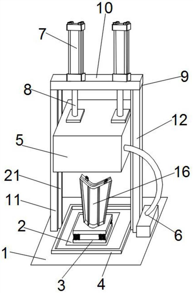
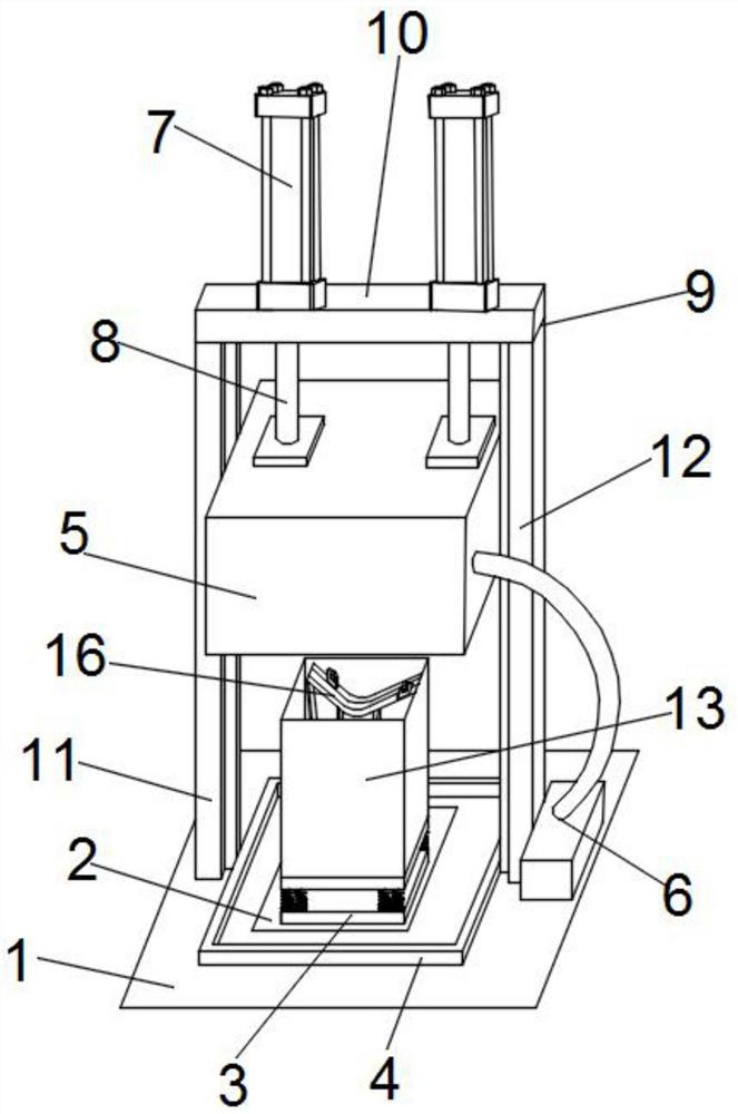
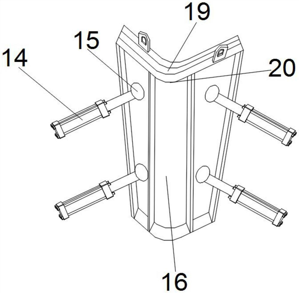
[0038] The following will be combined with the appendix in the embodiment of the present invention Figure 1-4 The technical solutions in the embodiments of the present invention are clearly and completely described, and obviously, the described embodiments are only a part of the embodiments of the present invention, rather than all the embodiments. Based on the embodiments of the present invention, all other embodiments obtained by those of ordinary skill in the art without creative efforts shall fall within the protection scope of the present invention.

[0039] The present invention provides a technical solution: a molding equipment and a molding process for realizing high-density refractory preforms, comprising a groove 2 recessed on the ground 1, a vibration table 3 is fixed in the groove 2, and is surrounded by a fixed In the gasket 4 on the ground 1, the upper part of the gasket 4 is provided with a sealing chamber 5 and the bottom edge of the sealing chamber 5 is align...


PUM


Abstract

The invention relates to the field of steelmaking, in particular to a molding device and a molding process for realizing high-density refractory prefabricated parts, comprising a groove recessed on the ground, a vibration table is fixed in the groove, and the groove is surrounded and fixed on the ground In the sealing gasket, the upper part of the sealing gasket is provided with a sealing chamber and the bottom edge of the sealing chamber is aligned with the sealing gasket. The side of the sealing chamber is connected with a negative pressure suction device, and the top surface of the sealing chamber is fixed at the end of the screw shaft of the cylinder. Fixed on the top plate of the fixed frame, the left support plate and the right support plate of the fixed frame are fixed on the ground, the left support plate and the right support plate are respectively fixed on the left and right outer sides of the gasket, vibrated by negative pressure , avoids the air from being drawn into the slurry from the outside of the mold during the vibration process, quickly discharges and exhausts the gas wrapped in the slurry, greatly improves the density of the preform, and can effectively resist the erosion of the slag. slag blocking effect.

Description

technical field [0001] The invention relates to the field of steelmaking, in particular to a molding device and a molding process for realizing high-density refractory preforms. Background technique [0002] Refractory materials have gone through the development stage from shape to shape, especially after the widespread use of ultrafine powder and superplasticizer in refractory materials, the high temperature performance of refractory castables has been greatly improved, and many parts using refractory bricks have been cast. It is used for the lining of thermal equipment. It can be directly baked and used without the firing process. Compared with refractory bricks, it has the advantages of simple process (because the firing process is omitted), energy saving, low cost and convenience. Mechanized construction and other characteristics, especially some functional parts, special-shaped parts, etc., it is very convenient to use casting molding; but the castable needs to be mixed...

Claims


Application Information

Patent Timeline
Patent Type & Authority Patents(China)
IPC IPC(8): B28B1/54B28B1/087B28B3/00B28B1/29B28B1/52
Inventor 严培忠翁小燕李国群俞鑫英虞畅
Owner 浙江红鹰铭德高温材料科技有限公司
Why Eureka
Try Eureka