
Conduction cooling type NbTi superconducting wire joint device and joint manufacturing method thereof

A joint device and superconducting wire technology, which is applied in the field of superconducting, can solve the problems of complex manufacturing process of superconducting coils, high hardness of ceramic phase, high brittleness, etc., and achieve the effect of tight electrical contact, low joint resistance, and reduced joint resistance

Pending Publication Date: 2022-04-01
HEFEI INSTITUTES OF PHYSICAL SCIENCE - CHINESE ACAD OF SCI
View PDF12 Cites 0 Cited by
  • Summary
  • Abstract
  • Description
  • Claims
  • Application Information

AI Technical Summary

Problems solved by technology

[0002] With the development of superconducting magnet technology, more and more magnetic fields in scientific research devices and facilities are generated by superconducting magnets. At present, low-temperature superconducting magnets in high-field magnetic field devices are mainly made of NbTi and Nb 3 Sn superconducting coil composition, compared with NbTi material, Nb 3 Although Sn has a high transition temperature, Nb 3 The manufacturing process of Sn superconducting coil is complicated, and heat treatment is required, and the ceramic phase formed after heat treatment has high hardness and high brittleness, which is easy to be formed in Nb 3 Inducing irreversible damage in Sn superconductors

Method used


Image

  • Conduction cooling type NbTi superconducting wire joint device and joint manufacturing method thereof
  • Conduction cooling type NbTi superconducting wire joint device and joint manufacturing method thereof
  • Conduction cooling type NbTi superconducting wire joint device and joint manufacturing method thereof

Examples


Embodiment Construction

[0036] The technical solutions in the embodiments of the present invention will be clearly and completely described below in conjunction with the accompanying drawings in the embodiments of the present invention. Obviously, the described embodiments are only part of the embodiments of the present invention, not all of them. Based on the embodiments of the present invention, all other embodiments obtained by persons of ordinary skill in the art without making creative efforts belong to the protection scope of the present invention.

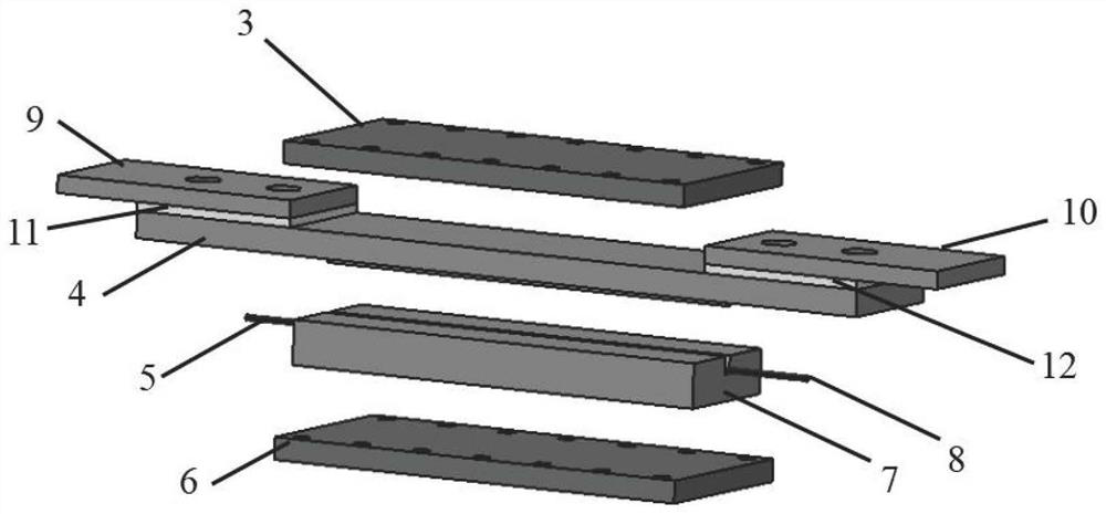
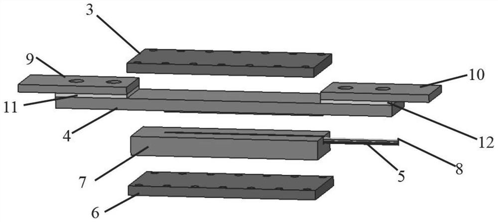
[0037] According to one embodiment of the present invention, a conduction cooling type NbTi superconducting wire joint device is proposed, such as Figure 1-3 As shown, it includes upper pressure plate 3, lower pressure plate 6, upper cover plate 4, lower cover plate 7, first cold guide plate 9, second cold guide plate 10, first insulating plate 11, second insulating plate 12, preload Bolts, insulating bolts; also include the first NbTi superconduc...


PUM


Abstract

The invention relates to a conduction cooling type NbTi superconducting wire connector device and a connector manufacturing method. A connector comprises an upper pressing plate, a lower pressing plate, an upper cover plate, a lower cover plate, a cold conduction plate, an insulating plate, a pre-tightening bolt, an insulating bolt, a superconducting wire and a superconducting wire connecting part. The invention discloses a manufacturing method of a conduction cooling NbTi superconducting wire joint. Corroding a copper substrate at the two ends of the superconducting wire for manufacturing the joint by using a FeCl3 solution to expose the NbTi filament; the filaments of the superconducting wires at the two ends needing to be connected are woven into a bundle; placing the connection part of the braided superconducting wire into a groove of a lower pressing plate, and adding low-temperature brazing filler metal; upper and lower pressing plates and upper and lower cover plates are placed on a heating table to be heated, so that the low-temperature brazing filler metal is thoroughly melted; covering the upper cover plate on the lower cover plate, and pre-tightening by using a pre-tightening screw; the manufactured connector device is placed and naturally cooled to the room temperature; and installing the insulating plate and the cold guide plate. The invention has the advantages of simple joint manufacturing process and equipment, stable and reliable structure and low joint resistance.

Description

technical field [0001] The invention belongs to the field of superconductivity, and mainly relates to a conductive cooling type NbTi superconducting wire joint device and a joint manufacturing method thereof. Background technique [0002] With the development of superconducting magnet technology, more and more magnetic fields in scientific research devices and facilities are generated by superconducting magnets. At present, low-temperature superconducting magnets in high-field magnetic field devices are mainly made of NbTi and Nb 3 Sn superconducting coil composition, compared with NbTi material, Nb 3 Although Sn has a high transition temperature, Nb 3 The manufacturing process of Sn superconducting coil is complicated, and heat treatment is required, and the ceramic phase formed after heat treatment has high hardness and high brittleness, which is easy to be formed in Nb 3 irreversible damage in Sn superconductors. Although the upper critical magnetic field of NbTi at 4....

Claims


Application Information

Patent Timeline
Patent Type & Authority Applications(China)
IPC IPC(8): H01R13/502H01R11/11H05K7/20H01R43/00
Inventor 郝强旺胡立标戴超武玉
Owner HEFEI INSTITUTES OF PHYSICAL SCIENCE - CHINESE ACAD OF SCI
Learn More