Oil-gas dual-purpose cylinder and control system thereof

A control system and dual-purpose technology, applied in the hydraulic field, can solve the problem of too fast opening and closing of the drive cylinder in the initial stage, and achieve good practicability and interoperability, good driving effect, and more stable driving effect

Pending Publication Date: 2022-04-05
ZHEJIANG HENGDAO TECH
View PDF3 Cites 0 Cited by
  • Summary
  • Abstract
  • Description
  • Claims
  • Application Information

AI Technical Summary

Problems solved by technology

In the above-mentioned prior art, the problem of hydraulic buffering is solved, but there is still the problem that the driving cylinder is opened and closed at an initial stage of too fast speed

Method used


Image

  • Oil-gas dual-purpose cylinder and control system thereof
  • Oil-gas dual-purpose cylinder and control system thereof
  • Oil-gas dual-purpose cylinder and control system thereof

Examples


specific Embodiment 1

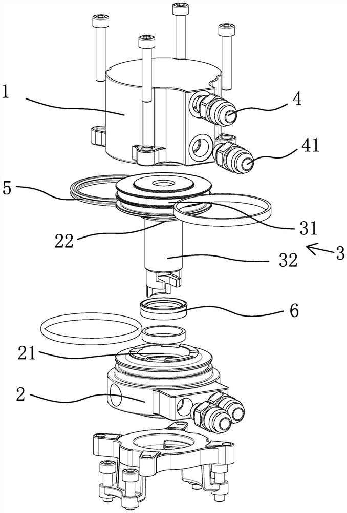
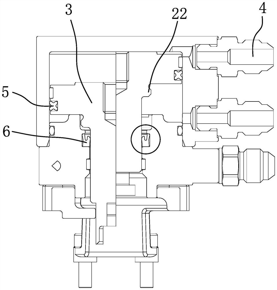
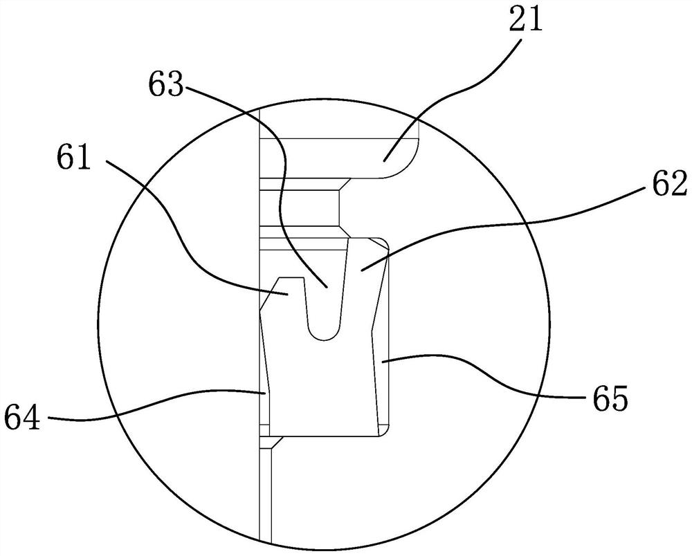
[0031] Specific embodiment 1 such as Figure 1-3 Shown: an oil-gas dual-purpose cylinder, including a cylinder body 1 and a cylinder head 2, a sealed cavity is formed between the cylinder body 1 and the cylinder head 2, and a piston 3 is arranged inside the cylinder body 1, so The cylinder body 1 is provided with a medium inlet 4 and a medium outlet 41 communicating with the cavity, the piston 3 includes a piston head 31 and a piston column 32, and the piston head 31 and the inner wall of the cylinder body 1 are provided with The first sealing ring 5, the self-sealing ring 6 that can change the contact stress between itself and the piston rod 32 with the change of medium pressure is arranged between the piston rod 32 and the cylinder head 2. The medium includes liquid medium and gas medium, that is, the oil-air dual-purpose cylinder can be used as an air cylinder or a hydraulic cylinder; in the scene where the oil-air dual-purpose cylinder is an air cylinder, the pressure of t...

specific Embodiment 2

[0035] Specific embodiment 2 such as Figure 4-7 Shown: a control system of an oil-air dual-purpose cylinder, which is used to control when the medium in the oil-air dual-purpose cylinder is liquid. The control system includes an oil tank, a power pump, and a two-position four-way reversing valve connected in sequence 7, and the throttle valve 71 and the two-position two-way valve 72 connected in parallel are finally connected to the hydraulic cylinder whose medium is liquid, and the throttle valve 71 and the two-position two-way valve 72 are used to control the oil and gas cylinder speed, when the two-position two-way valve 72 is opened, the hydraulic cylinder is in the first flow state; when the two-position two-way valve 72 is closed, the hydraulic cylinder is in the second flow state when the medium only passes through the throttle valve 71, and the first The flow rate is greater than the second flow rate; when the piston rod 32 is in the extended state to be retracted, th...

Embodiment 2

[0037] The working process of embodiment 2 is as follows: as Figure 4 After the valve needle 9 completes a round of injection molding work, the power pump in the control system inputs pressure oil into the rodless chamber of the hydraulic cylinder through the two-position four-way reversing valve 7, and the pressure oil in the rod chamber is transferred from the one-way speed regulating valve The check valve flows back to the oil tank, and now the valve needle 9 on the piston rod 32 enters a closed state.

[0038] Such as Figure 5 , when the next injection is about to start, the two-position four-way reversing valve 7 is energized to complete the switching between P and T ports, so that the pressure oil flows to the rod chamber. During this process, the one-way The throttle valve 71 restricts the pressure oil flow into the rod cavity according to the set throttle opening size, so as to control the opening speed of the valve needle 9, while the two-position two-way valve 72 ...


PUM


Abstract

The invention relates to an oil-gas dual-purpose cylinder and a control system thereof, belongs to the technical field of hydraulic pressure, and solves the problem that in the prior art, a hot melting channel needs to be provided with one air cylinder and one hydraulic cylinder. The oil-gas dual-purpose cylinder comprises a cylinder body and a cylinder cover, a sealed cavity is formed between the cylinder body and the cylinder cover, a piston is arranged in the cylinder body, a medium inlet and a medium outlet which are communicated with the cavity are formed in the cylinder body, the piston comprises a piston head and a piston column, and a first sealing ring is arranged between the piston head and the inner wall of the cylinder body. And a self-sealing ring capable of changing the contact stress with the piston column along with the change of the medium pressure is arranged between the piston column and the cylinder cover. In the scene of the air cylinder, the pressure of air is small, and the first sealing ring can independently seal the air; in the scene of a hydraulic cylinder, due to the fact that the pressure of a liquid medium is large, the first sealing ring cannot achieve sealing independently, the self-sealing ring is arranged to assist in achieving sealing, and due to the characteristics of the self-sealing ring, too large friction force cannot be generated in the air cylinder state.

Description

technical field [0001] The invention belongs to the field of hydraulic technology, in particular to an oil-air dual-purpose cylinder and a control system thereof. Background technique [0002] According to the gate form of the hot nozzle, the hot runner can be divided into open type and needle valve type. The so-called open type means that there is no active closing valve needle inside the gate for sealing the material, and the gate is closed mainly by relying on the front gate to generate a small section of cold plug to block the molten state of the rear end after the injection molding is completed. The plastic flows out to complete an injection molding cycle; the needle valve type, as the name implies, has a valve needle for sealing the material inside, and the movement of the valve needle matches the work of the injection molding machine to achieve reciprocating motion according to different injection molding signals, which can be realized Valve needle opening and closin...

Claims


Application Information

Patent Timeline
IPC IPC(8): F15B15/14F15B15/22F15B13/02F15B21/041F16J1/12F16J9/20F16J15/16F16K31/124B29C45/28
Inventor 王洪潮
Owner ZHEJIANG HENGDAO TECH
Why Eureka
Try Eureka