
Profile forming device and method for heat dissipation element with micro-channel offset layout

A technology of heat dissipation elements and micro-channels, applied in the direction of metal extrusion dies, etc., can solve the problems of die wear or cracking, affecting the shape and dimensional accuracy of profiles, and die core deflection, reducing die core offset and improving die. Longevity, reduced wear and eccentric loads

Active Publication Date: 2022-04-08
SHANDONG UNIV
View PDF8 Cites 2 Cited by
  • Summary
  • Abstract
  • Description
  • Claims
  • Application Information

AI Technical Summary

Problems solved by technology

This kind of profile with large wall thickness difference and microchannel offset layout requires a lot of extrusion force during its extrusion process, and there is a high local stress in the mold, which is easy to cause wear or cracking of the mold, which seriously affects the quality of the mold. Service life and profile accuracy; the material deformation is very severe during the extrusion process, especially for the profile extrusion of the micro-channel offset layout, the local deformation of the material is more severe, because the plastic deformation is converted into heat, which is easy to cause local temperature rise , which in turn affects the microstructure and mechanical properties of the profile; for the microchannel flat tube profile with unequal side wall thickness and large wall thickness difference, the internal channel size is small, so the core size of the extrusion die is also small, and the mold The difference in the feeding amount of the split holes on both sides will generate a large lateral thrust on the mold core, which will lead to stress concentration at the root of the mold core, resulting in the deflection of the mold core, which will cause obvious wall deviation of the profile and seriously affect the shape of the profile And dimensional accuracy, even lead to mold core fracture, it is difficult to meet the forming needs of profiles for heat dissipation elements with micro-channel offset layout

Method used


Image

  • Profile forming device and method for heat dissipation element with micro-channel offset layout
  • Profile forming device and method for heat dissipation element with micro-channel offset layout
  • Profile forming device and method for heat dissipation element with micro-channel offset layout

Examples


Embodiment 1

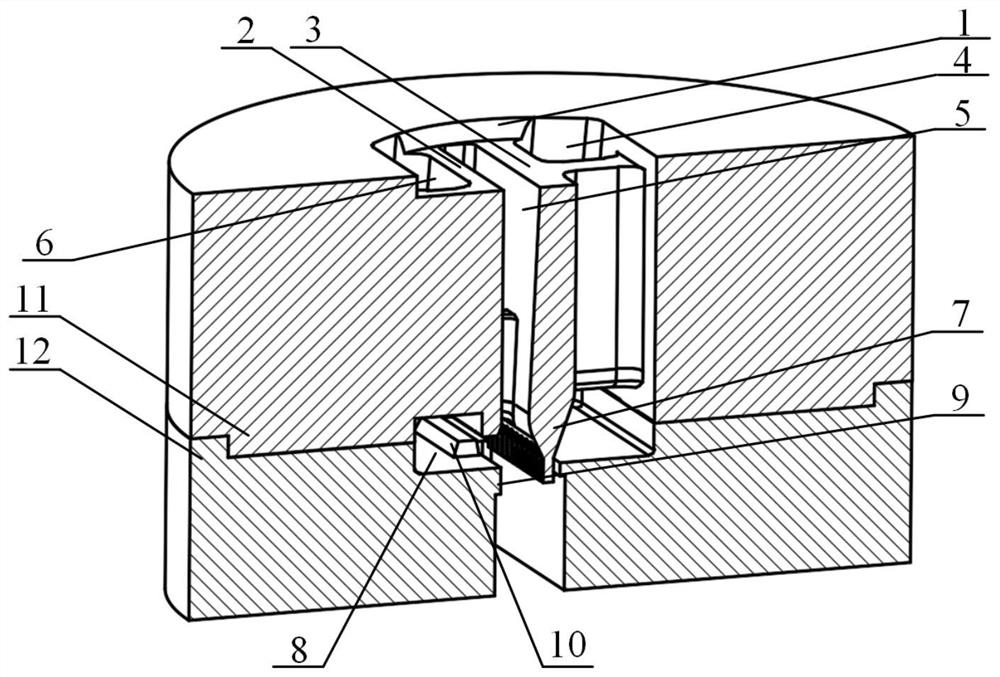
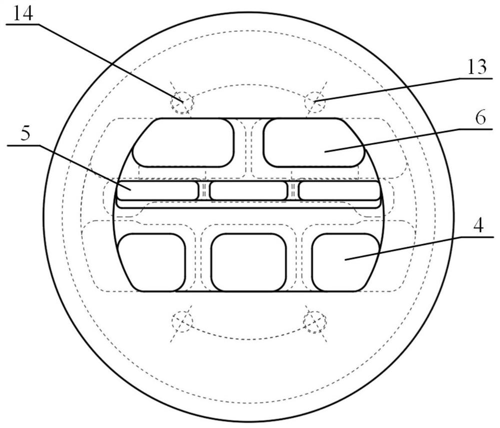
[0032] In a typical embodiment of the present invention, such as Figure 1 to Figure 5 As shown, a profile forming device for heat dissipation elements with a microchannel offset layout is given.

[0033] Such as figure 2 The profile forming device for the heat dissipation element of the microchannel offset layout shown is used for processing the profile for the heat dissipation element of the microchannel offset layout, such as figure 1 The profile 15 for the heat dissipation element with the microchannel offset layout is processed by the forming device to obtain the microchannel flat tube profile, and the profile 15 for the heat dissipation element with the microchannel offset layout is obtained after straightening and sawing. And through further machining, heat dissipation elements with micro-channel bias layout can be obtained, which can be applied to the heat dissipation of components inside the equipment, such as air conditioner inverters, diodes, etc., as a heat dissi...

Embodiment 2

[0060] In another typical embodiment of the present invention, such as Figure 1 to Figure 5 As shown, a profile forming method for a heat dissipation element with an offset layout is given, using a profile forming device for a heat dissipation element with an offset microchannel layout as in Example 1.

[0061] Include the following steps:

[0062] Homogenize the melted and cast bars, then saw and cut them as required to obtain a certain length of billet for extrusion, and then heat and keep the billet warm;

[0063] Preheat the mold and keep it warm, and send the heat-insulated extrusion billet into the material inlet of the mold;

[0064] The ingot for extrusion passes through the counterbore 1, the split hole, the welding chamber 8, the core drainage groove and the forming cavity sequentially in the mold, and is finally formed by the end of the working belt into a heat dissipation element profile 15 with a microchannel offset layout;

[0065] Cooling, straightening and s...


PUM

PropertyMeasurementUnit
Diameteraaaaaaaaaa
Heightaaaaaaaaaa

Abstract

The invention provides a profile forming device and method for a heat dissipation element with micro-channels arranged in an offset mode, and relates to the field of profile extrusion forming, the profile forming device comprises a mold, flow dividing holes, a mold core and a forming cavity are arranged in the mold, the flow dividing holes are formed in the two sides of the mold core respectively, the sectional areas of the flow dividing holes in the two sides are different, and a mold core needle at one end of the mold core stretches into a working tape; a forming cavity is formed between the mold core needle and the working tape, and the distance between the mold core needle and the thick-wall side working tape is larger than that between the mold core needle and the thin-wall side working tape; the shunting hole in one side of the mold core is communicated with the thick-wall side of the forming cavity through the welding chamber, and the shunting hole in the other side of the mold core is communicated with the thin-wall side of the forming cavity through the welding chamber; in order to solve the problem that an existing profile for a heat dissipation element with a micro-channel arranged in an offset mode is difficult to form, the diverting holes arranged in the offset mode are formed to reasonably divert metal, so that the wall thickness distribution requirement of the profile with the micro-channel arranged in the offset mode is met, stress on the two sides of a die core is balanced, die abrasion and unbalance loading are reduced, the forming precision of the profile is improved, and the service life of a die is prolonged.

Description

technical field [0001] The invention relates to the field of extrusion forming of profiles, in particular to a profile forming device and method for heat dissipation elements with microchannel offset layout. Background technique [0002] There are often many circuit heating modules in the equipment cabinet, resulting in large heat generation, and the high temperature environment is likely to reduce the reliability of the components. In order to ensure long-term stable operation, the heating modules need to be cooled, such as air conditioner inverters , correspondingly provided with cooling elements inside. At present, the traditional heat dissipation method for the heating module in the equipment cabinet is mostly air cooling. For example, the fan installed in the frequency converter quickly discharges the heat in the cabinet to the outside of the machine through the air outlet. At the same time, for high-power devices, such as diodes and other components, due to the high e...

Claims


Application Information

Patent Timeline
IPC IPC(8): B21C25/02B21C23/14
Inventor 赵国群王晓伟
Owner SHANDONG UNIV
Learn More