Metal part additive forming system and method

A technology for additive forming and metal parts, applied in the field of metal 3D printing, it can solve the problems of easy powder sputtering, easy clogging, and unsmooth powder falling, and achieve the effect of accurate powder take-up amount, smooth promotion, and improved reliability.

Active Publication Date: 2022-04-08
SICHUAN ENG TECHN COLLEGE
View PDF20 Cites 3 Cited by
  • Summary
  • Abstract
  • Description
  • Claims
  • Application Information

AI Technical Summary

Problems solved by technology

[0005] The purpose of the present invention is to provide a system and method for additive molding of metal parts to solve the problems of concentrated powder falling points in the upper powder box in the prior art, dense metal powder at the powder outlet that is easy to block, and falling powder that is easy to sputter. The resulting low utilization rate of the metal powder in the upper powder box and unsmooth powder falling

Method used


Image

  • Metal part additive forming system and method
  • Metal part additive forming system and method
  • Metal part additive forming system and method

Examples


Embodiment 1

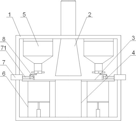
[0057] Such as Figure 1 to Figure 3 The shown metal parts additive molding system includes a molding chamber 1, a powder spreading platform 3 is arranged in the molding chamber 1, a molding cylinder 4 and a lower powder box 6 are arranged below the powder spreading platform 3, and a powder spreading platform 3 is arranged below the powder spreading platform 3. An upper powder box 5 is arranged above the platform 3, and a first driving device 7 is arranged on the powder spreading platform 3, and the first driving device 7 is used to drive the scraper 8 to transfer from the upper powder box 5 or the lower powder box 6 to the powder spreading platform. The metal powder on the platform 3 is scraped and sent to the molding cylinder 4 for printing, and the heat insulation frame 2 is arranged above the molding cylinder 4. The bottom of the upper powder box 5 is provided with a feeding tray 52, and the feeding tray 52 is provided with several The second through hole 521, the rotating...

Embodiment 2

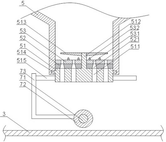
[0063] On the basis of Example 1, such as Figure 2 to Figure 5 As shown in a metal parts additive molding system, the rotating disk 51 is provided with a connecting column 512, the connecting column 512 moves through the feeding tray 52 and extends to the top of the feeding tray 52, the connection The column 512 is equipped with a stirring plate 53 located above the feeding tray 52, and the stirring plate 53 is provided with a plurality of third through holes 531. In the opened state, the third through holes 531 are connected to the first through holes. 511 and the second through hole 521 jointly constitute a feeding channel.

[0064] In some embodiments, the connecting column 512 is provided with a first agitating member 513 , and the diameter of the first agitating member 513 gradually decreases along the direction from the connecting column 512 to the inner wall of the upper powder box 5 .

[0065] In some embodiments, an annular second stirring member 532 is disposed on ...

Embodiment 3

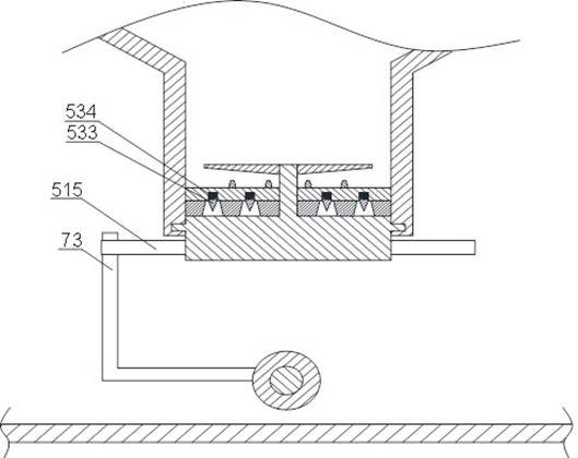
[0072] On the basis of Example 2, such as image 3 , Figure 6 to Figure 8 As shown, a first groove is provided on the lower surface of the stirring plate 53, a spring 534 is arranged in the first groove, and a scraper 533 is connected to the spring 534. In the open state, the The scraper 533 is entirely located in the first groove, and in the closed state, the scraper 533 enters into the second through hole 521 to scrape the metal powder in the second through hole 521 .

[0073] Such as Figure 8 As shown, in the open state, the scraper is entirely located in the first groove, and at this time the spring is compressed, and the bottom of the scraper abuts against the upper surface of the lower tray. Such as Figure 7 As shown, in the closed state, with the rotation of the agitating disc, the first groove is aligned with the second through hole, and the scraper that has lost its resistance is squeezed into the second through hole under the force of the spring, scraping 1. S...


PUM


Abstract

The invention discloses a metal part additive forming system and method.The system comprises a forming chamber, a powder laying platform is arranged in the forming chamber, a forming cylinder and a lower powder box are arranged below the powder laying platform, an upper powder box is arranged above the powder laying platform, and a first driving device is arranged on the powder laying platform; the first driving device drives the scraper to scrape and convey metal powder on the powder laying platform into the forming cylinder, a discharging disc is arranged at the bottom of the upper powder box, a plurality of second through holes are formed in the discharging disc, a rotating disc is arranged below the discharging disc, a plurality of first through holes are formed in the rotating disc, and a stirring piece is arranged on the first driving device. The motor is used for driving the rotating disc to switch between a closed state and an open state; in a closed state, the first through hole is not communicated with the second through hole; in the opening state, the first through hole and the second through hole are communicated to form a discharging channel, and the bottom end of the discharging channel is located between the scraper and the forming cylinder. According to the metal part additive forming system and method, powder falling is smooth, and the metal powder utilization rate is high.

Description

technical field [0001] The invention relates to the technical field of metal 3D printing, in particular to a system and method for additively forming metal parts. Background technique [0002] Additive manufacturing, also known as 3D printing, is to use software and numerical control system to accumulate special metal materials, non-metal materials and medical biological materials layer by layer according to extrusion, sintering, melting, light curing, spraying, etc., to manufacture physical objects manufacturing technology. [0003] Powder bed electron beam 3D printing is an additive manufacturing technology that builds up and melts metal powder layer by layer based on a digital model to produce a physical product. However, limited by the size of the powder bed electron beam additive manufacturing equipment itself and other structures inside the molding chamber, the size of the powder box is limited and the metal powder it can hold is limited. In order to solve this probl...

Claims


Application Information

Patent Timeline
Patent Type & Authority Applications(China)
IPC IPC(8): B22F12/52B22F12/67B22F10/28B22F10/73B33Y30/00B33Y40/00
Inventor 胡津李登万刘浩杜东方张永盛韩俊峰李忠利胡雅清
Owner SICHUAN ENG TECHN COLLEGE
Why Eureka
Try Eureka