Oil-cooled flat wire motor with cooling three-phase lead

A three-phase, oil-cooled technology, applied in the direction of cooling/ventilation devices, electrical components, electromechanical devices, etc., can solve the problems of low filling rate of round wire coils, poor heat dissipation effect, long winding ends, etc., to improve motor efficiency and reduce Effect of copper loss and small size

Pending Publication Date: 2022-04-08
中克骆瑞新能源科技有限公司
View PDF0 Cites 0 Cited by
  • Summary
  • Abstract
  • Description
  • Claims
  • Application Information

AI Technical Summary

Problems solved by technology

[0004] The purpose of the present invention is to address the above-mentioned deficiencies in the prior art, to provide an oil-cooled flat-wire motor with cooling three-phase leads, through cooling oil spraying, spraying, soaking, etc. , motor three-phase lead-out wires, and motor high-speed bearings for cooling and lubrica

Method used


Image

  • Oil-cooled flat wire motor with cooling three-phase lead
  • Oil-cooled flat wire motor with cooling three-phase lead
  • Oil-cooled flat wire motor with cooling three-phase lead

Examples


Embodiment Construction

[0023] The present invention will be described in further detail below in conjunction with the embodiments in the accompanying drawings, but this does not constitute any limitation to the present invention.

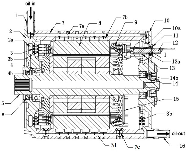
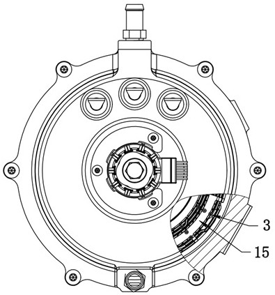
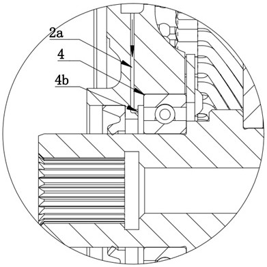
[0024] Such as figure 1 and figure 2 As shown, the present invention provides a kind of oil-cooled flat-wire motor with cooling three-phase leads, including casing 7, and front end cover 2 and rear end cover 10 installed at both ends of casing 7, front and rear end covers 2 and 10 is sealed and connected with the casing 7 to form a cooling oil chamber, the front bearing 4 and the rear bearing 14 are installed on the front end cover 2 and the rear end cover 10 respectively, the motor rotor 5 penetrates in the front and rear bearings, and the motor rotor 5 and the An oil seal 6 is arranged between the front end covers 2, the stator core 8 is fixed to the casing 7 through interference and keyway positioning, the flat wire armature 9 is embedded in the stator core 8, the th...


PUM


Abstract

The invention discloses an oil cooling flat wire motor with a cooling three-phase lead, which comprises a casing, a front end cover and a rear end cover, the front end cover and the rear end cover are mounted at two ends of the casing, the front end cover and the rear end cover are hermetically connected with the casing to form a cooling oil cavity, a front bearing and a rear bearing are mounted on the front end cover and the rear end cover respectively, and a motor rotor penetrates into the front bearing and the rear bearing. An oil seal is arranged between the motor rotor and the front end cover, the stator iron core is fixed to the machine shell through interference and key groove positioning, the flat wire armature is embedded into the stator iron core, and the three-phase outgoing line and the flat wire armature guide ring are welded to the flat wire armature. According to the oil-cooled flat wire motor, the modes of cooling oil spraying, spraying, soaking and the like are adopted, the motor end winding, the motor stator iron core, the motor three-phase outgoing line and the high-speed bearing for the motor are cooled and lubricated, the cooling efficiency is improved, the product stability is improved, and the cost is reduced.

Description


Claims


Application Information

Patent Timeline
Owner 中克骆瑞新能源科技有限公司
Why Eureka
Try Eureka