Method and device for gas burner

A burner and fuel technology, which is applied to burner control devices, gas turbine devices, burners, etc., can solve problems such as no disclosure.

Inactive Publication Date: 2004-03-24
UNITED TECH CORP
View PDF8 Cites 1 Cited by
  • Summary
  • Abstract
  • Description
  • Claims
  • Application Information

AI Technical Summary

Problems solved by technology

However, Stickler does not disclose the use of such a system for burning a premixed gaseous fuel / air mixture, but instead mentions premixing as a possible option

Method used


Image

  • Method and device for gas burner
  • Method and device for gas burner
  • Method and device for gas burner

Examples


Embodiment Construction

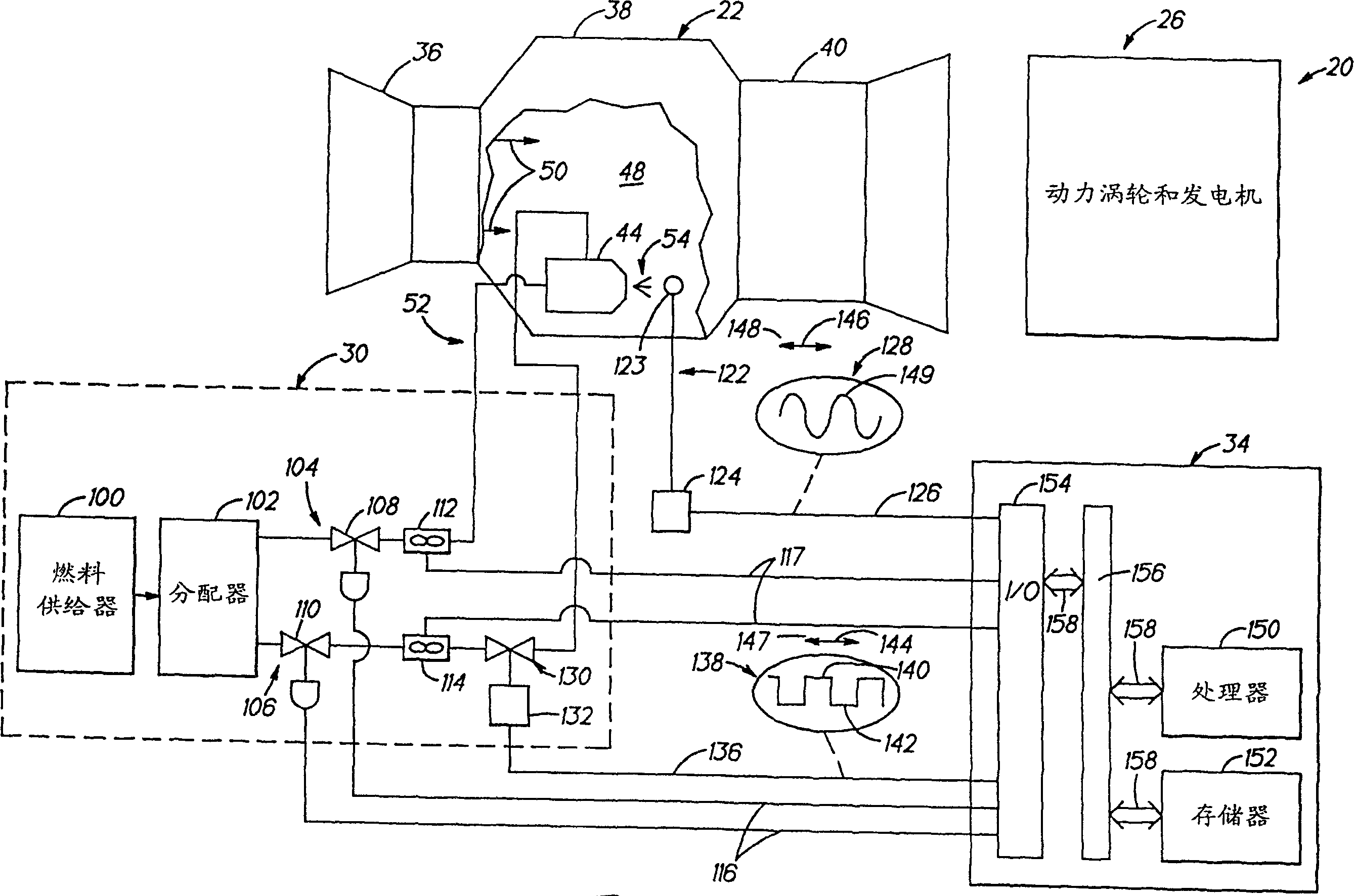
[0035] The invention disclosed herein is for figure 1 The preferred embodiment of the gas turbine power plant is shown. Gas turbine power plant 20 includes a gas turbine 22 , a power turbine and generator 26 , a fuel system 30 and a gas turbine controller 34 . The gas turbine receives fuel from fuel system 30 under the control of gas turbine controller 34 and combusts the fuel to drive power turbine and generator 26 .

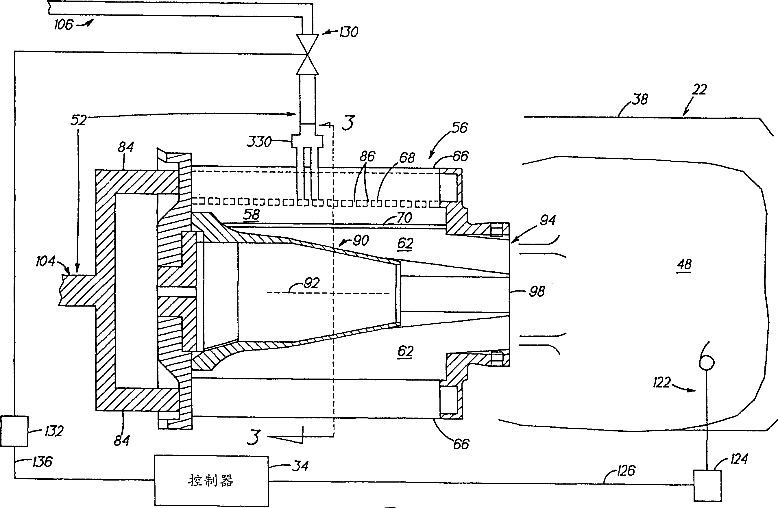
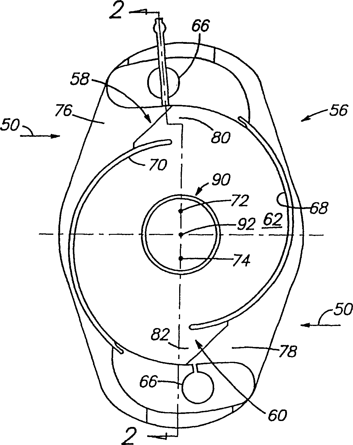
[0036] The gas turbine 22 includes a compressor 36 , a combustion section 38 (partially cut away for clarity) and a turbine 40 . Combustion section 38 typically includes a plurality, for example 16, of premixers (indicated by premixer 44 ) and a burner 48 . Premixers 44 may be spaced circumferentially about the upstream end of combustion section 38 . The burner 48 is preferably annular and is located downstream of the premixer 44 . The premixer receives and mixes compressed air 50 from compressor 36 and fuel provided from fuel system 30 by a plurality of fu...


PUM


Abstract

An apparatus for use in a system having a gas fuel supply and a combustor includes a fuel actuator, a controller; and a premixer. The controller generates a command signal indicative of actuation sought from the fuel actuator. The actuator receives gas fuel from the liquid fuel supply and provides liquid fuel at a modulated rate of flow in response to the command signal. The premixer receives the fuel from the actuator, mixes the fuel with air, and provides the mixture to the combustor.

Description

technical field [0001] The present invention relates to combustors, and more particularly to methods and apparatus for combustors using premixed gaseous fuel / air mixtures. Background technique [0002] Gas turbines are well known. A typical gas turbine has an annular, axially extending flow passage for sequentially passing a working fluid through a compression zone, a combustion zone, and a turbine zone. The combustion zone mixes the working fluid, typically air, with the fuel and ignites the fuel / air mixture. [0003] Gas turbines generally burn fossil fuels. An undesirable consequence of this combustion is the formation of nitrogen oxides, generally NO x express. Nitrogen oxides are pollutants that cause health and environmental problems. Government standards establish allowable No x Emissions to air. [0004] NO in gas turbine x The rate of generation of is directly dependent on the temperature in the combustion chamber. The combustion chamber temperature depends...

Claims


Application Information

Patent Timeline
Patent Type & Authority Patents(China)
IPC IPC(8): F23R3/36F02C3/22F02C9/28F23N5/16F23N5/18F23R3/28
CPCF23R2900/00014F23N5/16F23N2041/20F23R2900/00013F23N2025/04F23D2210/00F02C3/22F23D2208/00F23R3/286F23N2005/185F23N2225/04F23N2241/20F02C9/28
Inventor 杰弗里·M·科恩南希·M·雷伊冈萨洛·J·雷伊克拉斯·A·雅各布森
Owner UNITED TECH CORP
Why Eureka
Try Eureka