Laser cutting equipment with dustproof heat dissipation box

A laser cutting and cooling box technology, which is applied in laser welding equipment, welding equipment, metal processing equipment, etc., can solve the problems of dust and debris entering the control box, affecting the smooth cutting, and damage to internal components, so as to maintain ventilation Heat dissipation effect, convenient and fast removal, good for collection and adsorption

Inactive Publication Date: 2022-04-12
徐州赛福电子有限公司
View PDF0 Cites 0 Cited by
  • Summary
  • Abstract
  • Description
  • Claims
  • Application Information

AI Technical Summary

Problems solved by technology

[0004] When the large-scale laser cutting robot arm is in use, it is necessary to dissipate heat from the control box. Ventilation holes and external cooling methods are usually adopted. However, the use of various electronic devices at the inner end of the control box tends to generate excessive heat inside. If the heat is not dissipated in time, it is easy to cause damage to the internal components, which will affect the smooth progress of cutting. At the same time, the simple setting of the ventilation hole will easily make the dust and debris generated during the cutting process enter the inside of the control box, thereby causing internal pollution. , or even damage the machine, for this reason, we propose a laser cutting equipment with a dust-proof cooling box to solve the above problems

Method used


Image

  • Laser cutting equipment with dustproof heat dissipation box
  • Laser cutting equipment with dustproof heat dissipation box
  • Laser cutting equipment with dustproof heat dissipation box

Examples


Embodiment

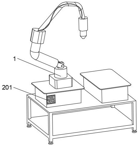
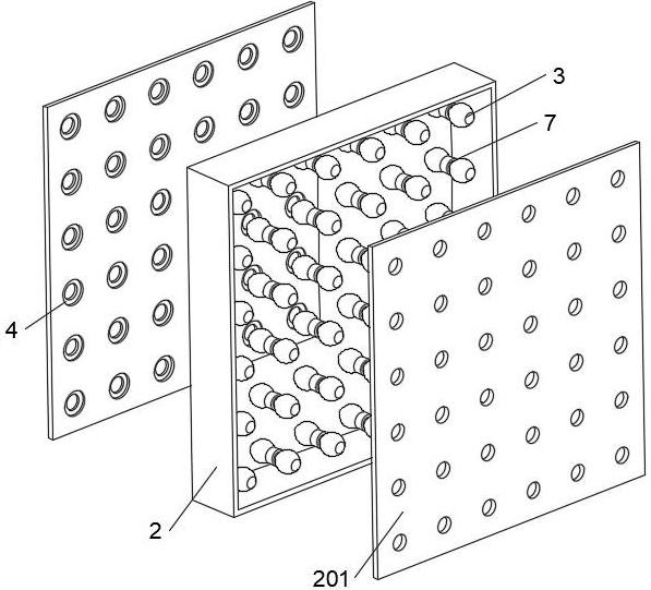
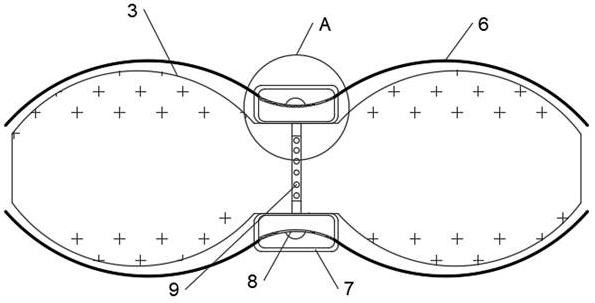
[0042] see Figure 1-Figure 10 , a laser cutting device with a dust-proof heat dissipation box, including a laser cutting device body 1, a heat dissipation channel 2 is fixedly installed on the laser cutting device body 1, and a ventilation plate 201 is fixedly connected to the front and rear ends of the heat dissipation channel 2 symmetrically. A plurality of air-distributing films 3 are fixedly connected between each ventilation plate 201, and a side of the ventilation plate 201 at the rear end close to the heat dissipation channel 2 is provided with a plurality of peeling ring placement grooves 4, and the sides of the two ventilation plates 201 are close to each other. A plurality of micro-heating sheets 5 are fixedly installed, and the side of the micro-heating sheets 5 close to the heat dissipation channel 2 is fixedly connected with a plurality of heat-sensitive driving ropes 6, and an extruded peeling ring 7 is slidably connected in the peeling ring placement groove 4, a...


PUM


Abstract

The invention discloses laser cutting equipment with a dustproof heat dissipation box, and belongs to the field of laser cutting equipment.The laser cutting equipment with the dustproof heat dissipation box comprises a laser cutting device body, a heat dissipation channel is fixedly installed on the laser cutting device body, and ventilation plates are symmetrically and fixedly connected to the front end and the rear end of the heat dissipation channel; a plurality of stripping ring containing grooves are formed in the side, close to the heat dissipation channel, of the ventilation plate located at the rear end, the extrusion stripping rings and the air uniformizing film are additionally arranged in the heat dissipation channel to be used in cooperation, dust adhering to the interior of the air uniformizing film is stripped, dust and powder are collected and removed through movement of the electrostatic adsorption rings on the air uniformizing film, and therefore the dust removal efficiency is improved. And therefore, the purpose of conveniently and rapidly removing the dust in the heat dissipation channel is achieved, the ventilation and heat dissipation effects of the heat dissipation channel are effectively kept, the working efficiency of the laser cutting device body is effectively improved, and the service life of the laser cutting device body is effectively prolonged.

Description

technical field [0001] The invention relates to the field of laser cutting equipment, more specifically, to a laser cutting equipment with a dust-proof cooling box. Background technique [0002] Cutting equipment refers to the continuous casting equipment that cuts the continuously drawn slabs according to the length requirements. Cutting machines are divided into metal material cutting machines and non-metallic material cutting machines from the cutting materials. Metal material cutting machines are divided into flame cutting machines, plasma cutting machines, laser cutting machines, water jet cutting machines, etc.; non-metallic material cutting machines Mainly knife cutters. [0003] As a new type of thermal cutting technology, laser cutting has the advantages of fast cutting speed, high production efficiency, good cutting end surface quality, small heat-affected zone and environmental protection. It has become one of the main sheet metal cutting methods and has been wid...

Claims


Application Information

Patent Timeline
Patent Type & Authority Applications(China)
IPC IPC(8): B23K26/70B23K26/38
Inventor 高宏国高洪福
Owner 徐州赛福电子有限公司
Why Eureka
Try Eureka