Online health monitoring system and method for conveyor belt carrier roller based on resonance cavity wire spool

A health monitoring system and winding reel technology, applied in the direction of rollers, conveyors, conveyor objects, etc., can solve problems such as tearing, tape burning, tape breaking, etc., to reduce the impact of background noise and eliminate accumulated errors. , the effect of improving the accuracy

Pending Publication Date: 2022-04-12
NANJING FAAIBO OPTOELECTRONICS TECH +1
View PDF1 Cites 0 Cited by
  • Summary
  • Abstract
  • Description
  • Claims
  • Application Information

AI Technical Summary

Problems solved by technology

The long-term operation of the idler can lead to the following two major problems: the bearing of the idler is necrotic during operation, and the rigid friction with the belt is overheated to accelerate aging. In severe cases, the belt can be burned and the entire conveyor belt is paralyzed; the idler is loose during operation. Dropped, rolled to the drum by the return tape to cause the tape to break through or tear, which will cause huge economic losses
[0006] Question 1. In the patent "DAS-based Fault Monitoring Method for Trough Idler of Belt Conveyor" (Application No. 202010920154.8), it is mentioned that the optical fiber ring is directly placed on the bracket and the bottom of the idler. First of all, such an operation is very difficult , it takes a long time to stop the conveyor belt for layout, and the optical fiber is also very easy to be pulled and broken during the operation of the conveyor belt
However, in the actual conveyor belt roller monitoring, the stick-type bracket cannot be quickly installed on the roller bracket, and the design of the circular winding reel results in that in order to meet the width limit of the roller support groove, the optical cable wound by the circular winding reel very limited length
The design of pure aluminum alloy will also cause the vibration of the roller to be transmitted to the optical cable, and the noise part will also be transmitted together. There is no sensitivity enhancement for the specific observation frequency band, and the sensitivity is poor.
[0008] Question 3: In the monitoring method that has been proposed, when actually monitoring the health of the idlers, the noise level during the operation of the conveyor belt is high, and the characteristic changes of the idlers that need to be paid attention to are very subtle. If no targeted sensitization measures and algorithms are taken It is difficult to detect whether the idler has potential safety hazards, or the system makes a large number of misjudgments, resulting in low reliability

Method used


Image

  • Online health monitoring system and method for conveyor belt carrier roller based on resonance cavity wire spool
  • Online health monitoring system and method for conveyor belt carrier roller based on resonance cavity wire spool
  • Online health monitoring system and method for conveyor belt carrier roller based on resonance cavity wire spool

Examples


Embodiment 1

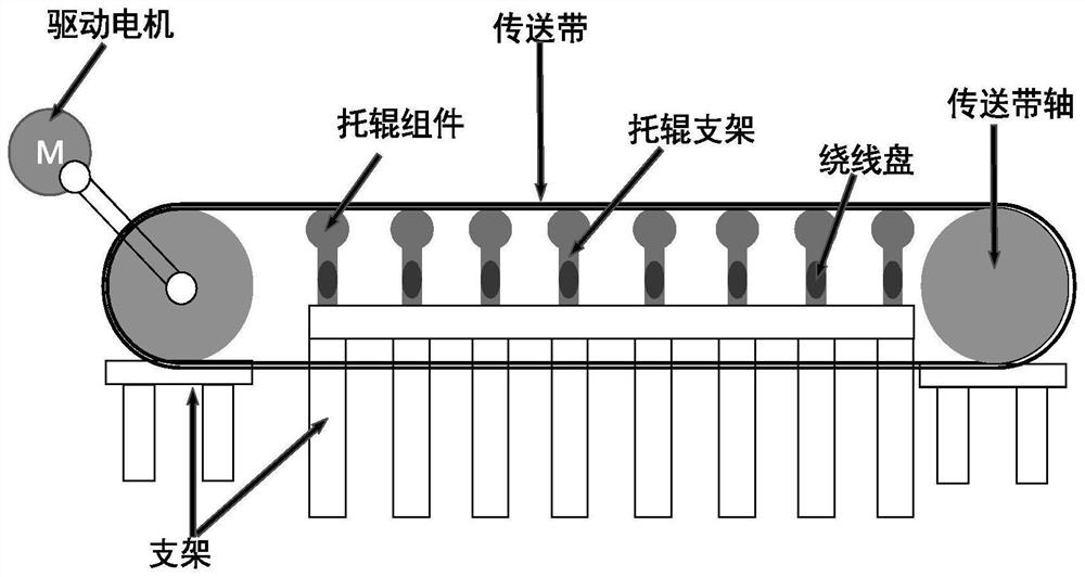
[0064] The embodiment of the present invention proposes an online health monitoring system for conveyor rollers based on resonant cavity winding reels. The monitoring system includes optical cables, distributed optical fiber vibration sensing systems and m winding reels with resonant cavity, where m is A positive integer greater than or equal to 2.

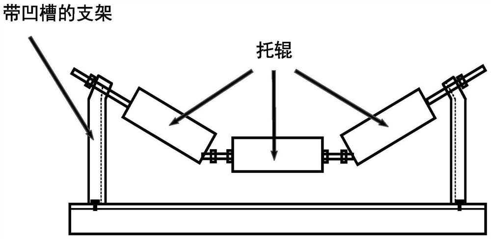
[0065] The m winding reels with resonance chambers are installed in the grooves of the m idler brackets one by one, the optical cables are tightly wound on the m resonating chamber winding reels in turn, and the optical cables wound on the winding reels lengthL 2 Cable length L between idlers corresponding to adjacent winding reels 1 The sum meets one or several spatial resolution requirements; the length of the optical cable before the first reel is (L 1 +L 2 )×n, n is a positive integer.

[0066] The distributed optical fiber vibration sensing system is connected to the end of the optical cable. When the conveyor belt stops ...

Embodiment 2

[0088] An embodiment of the present invention proposes an online health monitoring method for conveyor belt rollers based on a resonant cavity winding reel. The monitoring method includes the following steps:

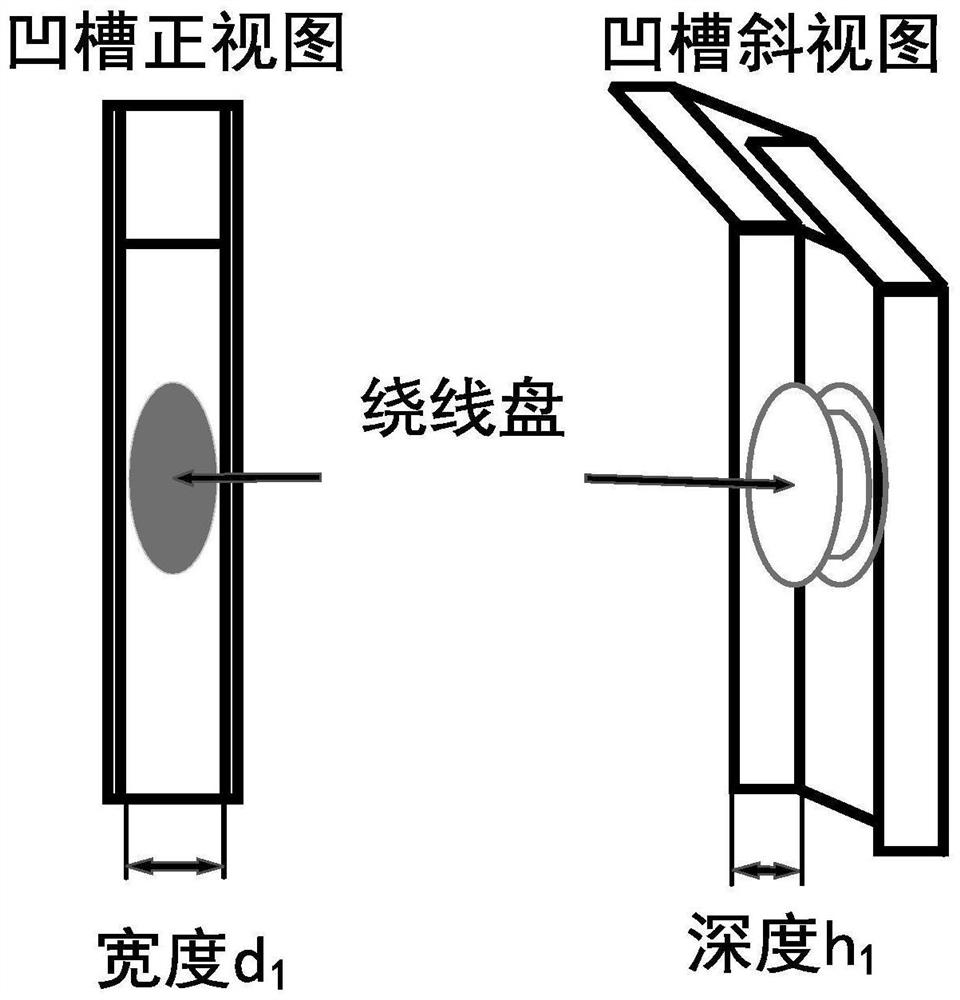
[0089] S1, measure the idler rollers of the conveyor belt to be monitored, and count the number of idler sets of the conveyor belt, the distance between the idler sets, the groove width and groove depth on the idler brackets.

[0090] S2, according to the parameters counted in step S1, fabricate the reel with resonance cavity as mentioned above.

[0091] S3, the optical cable is wound on the winding reel in turn, and then the winding reel is adsorbed in the groove of the idler bracket to be monitored one by one, and the optical cable is connected to the distributed optical fiber vibration sensing system.

[0092] S4, stop the conveyor belt, tap the rollers to be monitored one by one for 5 times, the distributed optical fiber vibration sensing system analyzes the collect...


PUM


Abstract

The invention discloses a conveyor belt carrier roller online health monitoring system based on resonance cavity wire spools. The conveyor belt carrier roller online health monitoring system comprises an optical cable, a distributed optical fiber vibration sensing system and m wire spools with resonance cavities. The wire reels with resonance cavities are installed in grooves of the carrier roller supports, the optical cable is sequentially and tightly wound on the m resonance cavity wire reels, and the sum of the length of the optical cable wound on the wire reels and the length of the optical cable between the carrier rollers corresponding to the adjacent wire reels meets the requirement for one or more spatial resolutions. When the conveyor belt runs, the distributed optical fiber vibration sensing system analyzes the quality factor of the vibration frequency and the resonance frequency change of each carrier roller observation point, and diagnoses and identifies the faulted carrier roller. The optical cable winding disc with the resonance cavity is used for scientifically and efficiently arranging the optical cable to be measured, and all-weather real-time health monitoring on the conveyor belt carrier roller is achieved through a carrier roller health data processing method.

Description

technical field [0001] The invention relates to the technical field of distributed optical fiber sensing, in particular to an online health monitoring system and method for conveyor belt rollers based on resonant cavity winding reels. Background technique [0002] With the development of industrialization, conveyor belt systems are also spread across various factories, mines and construction sites. As the conveyor belt system works, generally speaking, the idler part of the conveyor belt system is the first to wear out. Monitoring the health of the idler rollers is the most important thing to ensure the normal operation of the conveyor belt system. [0003] Take the conveyor belt system for transporting coal as an example, usually the distance between idlers is 0.8m, and a conveyor belt system usually has dozens of idlers. The long-term operation of the idler can lead to the following two major problems: the bearing of the idler is necrotic during operation, and the rigid f...

Claims


Application Information

Patent Timeline
Patent Type & Authority Applications(China)
IPC IPC(8): B65G15/60B65G43/00B65G39/12
Inventor 张驰彭程程赵世松邹宁睦柏顺娣
Owner NANJING FAAIBO OPTOELECTRONICS TECH
Why Eureka
Try Eureka