
Energy-saving building material drying device

A technology of building materials and drying equipment, which is applied in the direction of drying gas arrangement, progressive dryer, drying solid materials, etc., can solve the problems of reduced performance, incomplete drying, and low work efficiency, so as to improve adaptability and promote drying. Dry efficiency, not easy to accumulate effect

Pending Publication Date: 2022-04-12
蓝山永佳建筑材料有限公司
View PDF10 Cites 0 Cited by
  • Summary
  • Abstract
  • Description
  • Claims
  • Application Information

AI Technical Summary

Problems solved by technology

[0005] Aiming at the deficiencies of the prior art, the present invention provides an energy-saving building material drying device, which solves the problem that the existing building material drying device tends to accumulate some granular or massive building materials. When drying, only To dry the surface, the materials buried at the bottom cannot be dried, so that the drying is not complete, and multiple dryings are required, which is time-consuming and laborious, and the work efficiency is low, which reduces the problem of performance

Method used


Image

  • Energy-saving building material drying device
  • Energy-saving building material drying device
  • Energy-saving building material drying device

Examples


Embodiment example 1

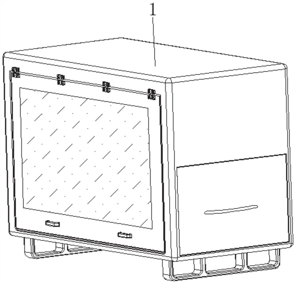
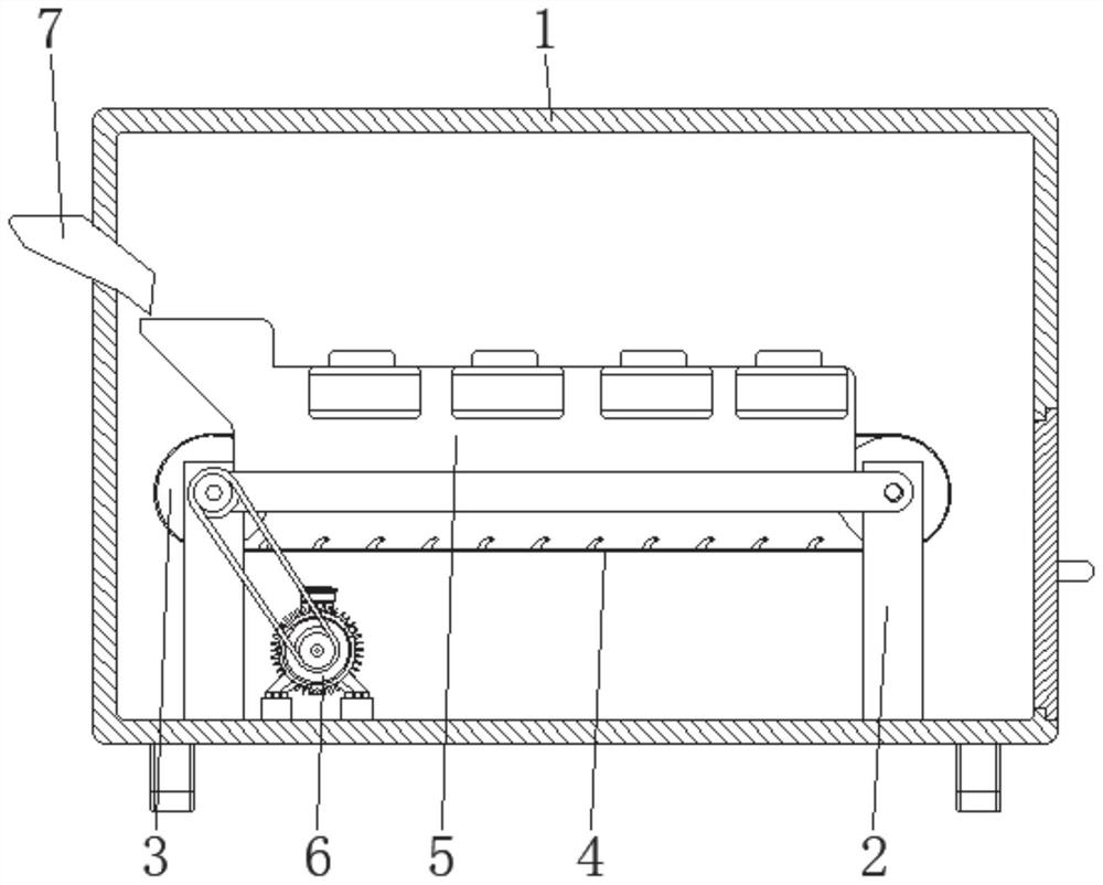
[0034] see Figure 1-7 , the present invention provides a technical solution: an energy-saving drying device for building materials, including a body 1, a bracket 2, a transmission roller 3, a conveying device 4, and a drying device 5, and the bottom of the bracket 2 is fixedly connected to the bottom of the inner wall of the body 1 , the end of the drive roller 3 is rotatably connected to the top of the support 2 and is located at the end position, the conveying device 4 is arranged on the surface of the drive roller 3, and the drying device 5 is arranged on the top of the support 2 and close to the position of the conveying device 4;

[0035] The bottom of the inner wall of the body 1 is fixedly connected with a servo motor 6, the output shaft of the servo motor 6 is connected to one end of the drive roller 3 through a belt transmission assembly, and the side of the surface of the body 1 and one end close to the drying device 5 is provided with a feed The bucket 7 uses the s...

Embodiment example 2

[0037] Conveying device 4 is provided with elastic conveying net 41, rubber edge 42, beading device 43, and elastic conveying net 41 is arranged on the surface of drive roller 3, and rubber edge 42 is arranged on the two sides corresponding to elastic conveying net 41 surface edges, and beading device 43 It is arranged on the inner wall of the elastic conveying net 41 .

[0038] The elastic conveying net 41 is set as a closed loop, the rubber edge 42 is set as a closed loop, and the pressing device 43 is evenly distributed on the inner wall of the elastic conveying net 41 .

[0039] Beading device 43 is provided with beading main body 431, ball 432, and one end of beading main body 431 is fixedly connected with the inwall of elastic conveying network 41, and the surface of beading main body 431 is set as arc surface, and ball 432 is rollingly connected on the surface of beading main body 431, utilizes The rotation of the transmission roller 3 drives the elastic conveying net 4...

Embodiment example 3

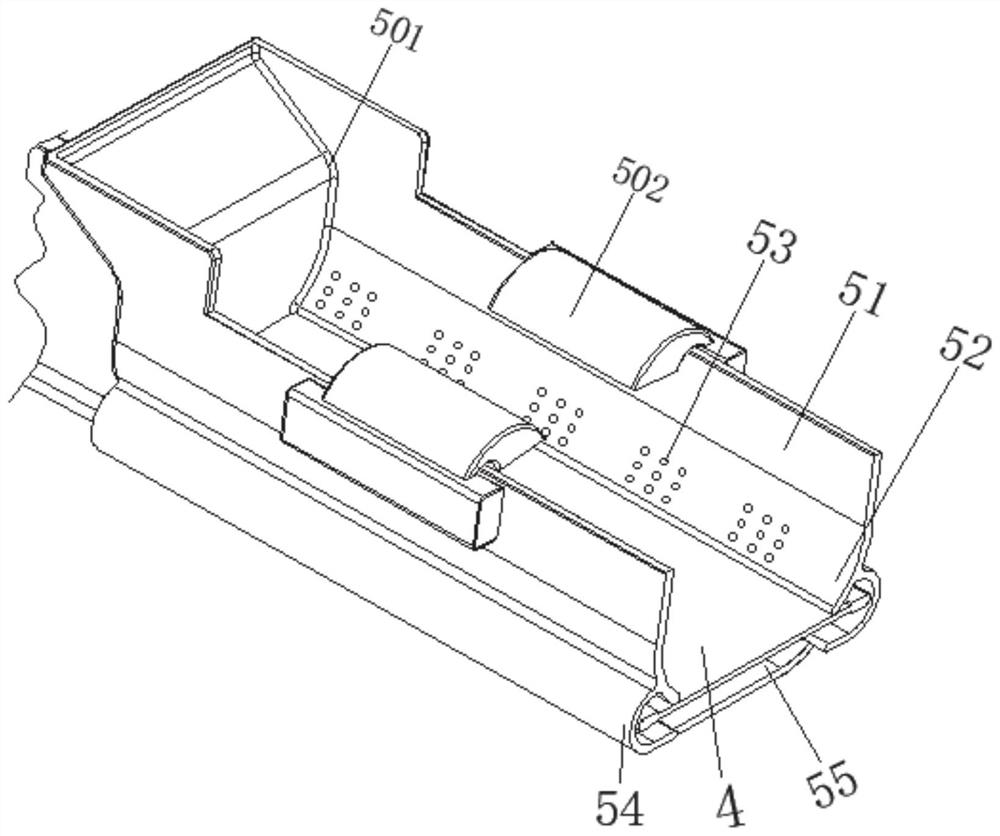
[0041] The drying device 5 is provided with a side plate 51, an arc-shaped inner concave surface 52, an air injection hole 53, an arc-shaped housing 54, and a pressure outlet device 55. The arc-shaped inner concave surface 52 is arranged on the surface bottom of the side plate 51, and the air injection hole 53 is provided. Inside the arc-shaped concave surface 52 and at the position of the arc-shaped concave surface 52, the arc-shaped housing 54 is arranged on the bottom of the surface of the side plate 51 and on the side away from the air injection hole 53. The surface of the arc-shaped housing 54 is in contact with the bracket 2 The top is fixedly connected, and the pressurized air outlet device 55 is arranged at the bottom of the arc-shaped housing 54 and close to the position of the conveying device 4;

[0042] The pressurized air outlet device 55 is provided with a base plate 551, a pressing device 552, an elastic member 553, and an elastic air bag 554. The end of the base...


PUM


Abstract

The invention discloses an energy-saving building material drying device which comprises a machine body, a support, a transmission roller, a conveying device and a drying device, the conveying device is arranged on the surface of the transmission roller, the drying device is arranged at the top of the support and close to the position of the conveying device, and an air spraying hole is formed in an arc-shaped inwards-concave face and located in the position of the arc-shaped inwards-concave face. The pressed air outlet device is arranged at the bottom of the arc-shaped shell and close to the conveying device, the pressing device is arranged at the top of the base plate, the elastic piece is arranged between the two corresponding sides of the surface of the pressing device and the top of the base plate, and the elastic air bag is arranged between the two corresponding sides of the surface of the pressing device and the top of the base plate and close to the elastic piece. The invention relates to the technical field of building material drying equipment. According to the energy-saving type building material drying device, the rapid drying effect is achieved, materials can be turned over, the accumulation situation is not prone to occurring, rapid and thorough drying is facilitated, and the working efficiency and the using performance are improved.

Description

technical field [0001] The invention relates to the technical field of building material drying equipment, in particular to an energy-saving building material drying device. Background technique [0002] Building materials are a general term for materials used in civil engineering and construction engineering. New building materials include a wide range, including thermal insulation materials, heat insulation materials, high-strength materials, and breathing materials, all of which are new materials. Building materials are various materials used in construction engineering. There are many kinds of building materials, which can be divided into: inorganic materials, which include metal materials (including ferrous metal materials and non-ferrous metal materials) and non-metal materials (such as natural stone, burnt earth products, cement, concrete and silicate products, etc.). Organic materials, which include plant materials, synthetic polymer materials (including plastics, p...

Claims


Application Information

Patent Timeline
Patent Type & Authority Applications(China)
IPC IPC(8): F26B15/18F26B21/00F26B25/00F26B25/02F26B25/04
Inventor 彭艳秀
Owner 蓝山永佳建筑材料有限公司
Learn More