Fiber Optic Gyroscope and Its Relative Intensity Noise Optical Suppression Method

A technology of fiber optic gyroscope and fiber optic ring, which is applied in the direction of Sagnac effect gyroscope, etc., can solve the problems of large size, high price, and increased algorithm complexity, and achieve the effect of compact structure, easy assembly, and high stability

Active Publication Date: 2022-06-03
SHENZHEN OSNAV IND CO LTD
View PDF0 Cites 0 Cited by
  • Summary
  • Abstract
  • Description
  • Claims
  • Application Information

AI Technical Summary

Problems solved by technology

However, this solution needs to increase the detector and acquisition device, and add a demodulation module from the algorithm, which increases the complexity of the algorithm
[0009] (3) Add a Faraday rotating mirror and an optical attenuator at the dead end of the coupler to balance the two beams of light to achieve relative intensity noise suppression, but the Faraday rotating mirror also has the problem of large size and high price

Method used


Image

  • Fiber Optic Gyroscope and Its Relative Intensity Noise Optical Suppression Method
  • Fiber Optic Gyroscope and Its Relative Intensity Noise Optical Suppression Method
  • Fiber Optic Gyroscope and Its Relative Intensity Noise Optical Suppression Method

Examples


Embodiment Construction

[0038] As one embodiment, the Sagnac reflector has tunable loss and orthogonal rotation of polarization. The present invention is used in a fiber optic gyroscope

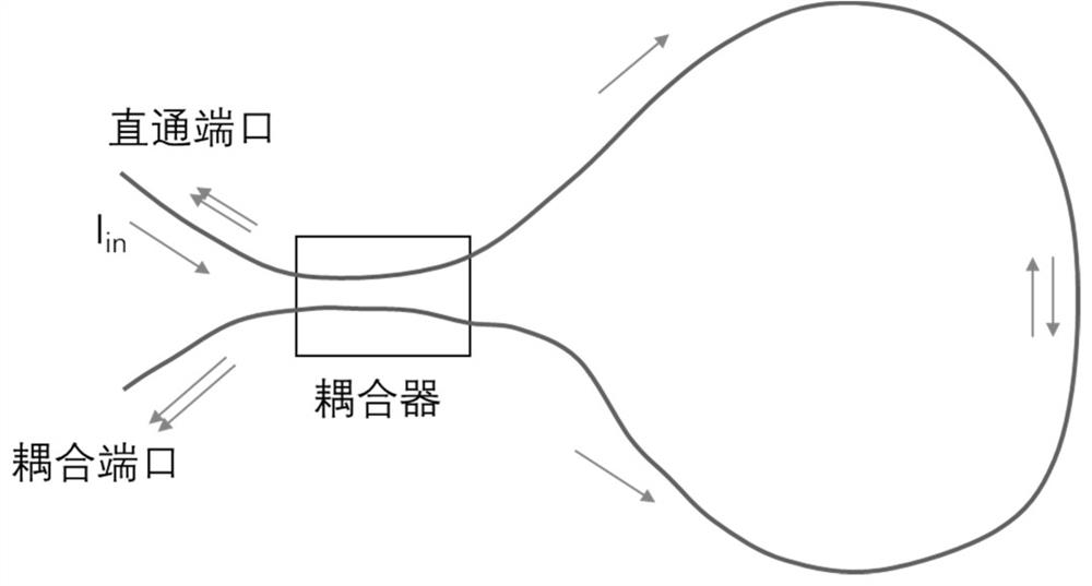
[0047] Wherein is the splitting ratio, is the input light intensity, is the phase difference between the forward and reverse two beams of light.

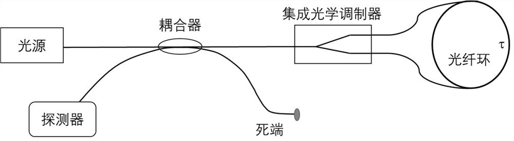
[0063] The optical path of the present invention is shown in Figure 5.

[0065] At the dead end of the coupler, a Sagnac reflector is installed. The reflector can be made of a polarization-maintaining coupler, which combines polarization-maintaining

[0066] The splitting ratio of the coupler can be calculated according to formula (1) according to the loss of the main optical path. The reflected light path should be aligned with the main light path

[0067] When the modulation is 3 / 4π, the insertion loss of the main optical path is about 18dB, and it can be calculated that a 99:1 coupler should be selected.

[0068] When the modulation is 1 / 2π, the loss of the main optical ...


PUM


Abstract

The embodiment of the invention discloses a fiber optic gyroscope and its relative intensity noise optical suppression method. The gyroscope includes a light source, a coupler, a detector, an integrated optical modulator, and an optical fiber ring. The tail fiber of the light source is provided with a polarization filter. The polarization filter converts the input light of any polarization state into linearly polarized light, and the main axis of the linearly polarized light is parallel to the polarization passing axis of the integrated optical modulator; the dead end of the coupler is provided with a Sagnac reflector, and the Sagnac reflector The device superimposes the reflected light and the main light autocorrelation intensity of the fiber optic gyroscope, so as to eliminate the influence of the coherence effect on the noise suppression. The invention utilizes the design of the all-fiber device, and realizes the suppression of the relative intensity noise of the light source at low cost without changing the circuit and the algorithm, and realizes the improvement of the signal-to-noise ratio of the gyroscope.

Description

Fiber Optic Gyroscope and Its Relative Intensity Noise Optical Suppression Method technical field The present invention relates to the optical fiber gyro technical field, relate in particular to a kind of optical fiber gyro and relative intensity noise optical suppression manufacturing method. Background technique The gyroscope is used for the rotational angular velocity of the sensitive carrier, and the fiber optic gyroscope of the three-axis orthogonal installation can be used to establish the space of the movement [0002] The inter-coordinate system is the basis for motion measurement and control. According to its working principle, gyroscope can be divided into mechanical gyroscope, laser gyroscope, optical gyroscope Fiber gyroscope, micromachined gyroscope, etc. The fiber optic gyroscope is based on the Sagnac interferometer, which uses the interference of the forward and reverse beams to achieve the rotational angular velocity Degree measurements, no moving pa...

Claims


Application Information

Patent Timeline
Patent Type & Authority Patents(China)
IPC IPC(8): G01C19/72
Inventor 刘晓平李汉舟焦峰
Owner SHENZHEN OSNAV IND CO LTD
Why Eureka
Try Eureka