
PIC-based pelvic floor muscle rehabilitation instrument

A pelvic floor muscle and triode technology, applied in the field of rehabilitation instruments, can solve the problems of reducing power consumption, secondary infection, affecting social and personal image, etc., to achieve the effect of reducing power consumption and cost

Pending Publication Date: 2022-04-15
湖南薇恺医疗科技有限公司
View PDF0 Cites 0 Cited by
  • Summary
  • Abstract
  • Description
  • Claims
  • Application Information

AI Technical Summary

Problems solved by technology

[0004] 1. Urinary incontinence (due to the relaxation of the pelvic floor muscles, the position of the bladder neck is relatively lowered, and it is easy to leak urine when laughing, coughing, sneezing, or lifting heavy objects, which seriously affects social and personal image);
[0005] 2. Pelvic floor organ prolapse;
[0006] 3. Abnormal abdominal pressure increases the burden on the muscles of the lower back (abnormal changes in abdominal pressure cause the gravity line to move forward, the lumbar spine protrudes and the force on the lower back increases, and the muscles become more and more tense);
[0007] 4. It is easy to induce secondary infection (the mucous membrane becomes thinner, which may reduce the body's immunity and increase the chance of infection);
[0013] 1. Since the circuit size space of the product is generally small, and the booster circuit required by the pelvic floor muscle rehabilitation instrument uses more electronic components, the product size has to be increased, resulting in increased product cost and bloated appearance;
[0014] 2. It is impossible to judge whether there is an external load connected, which makes it impossible to perform standby and reduce power consumption when there is no load connected

Method used


Image

  • PIC-based pelvic floor muscle rehabilitation instrument

Examples


Embodiment Construction

[0037] In order to enable those skilled in the art to better understand the present invention, the technical solution of the present invention will be further described below in conjunction with the accompanying drawings and embodiments.

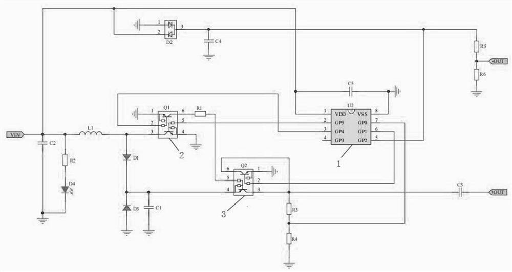
[0038] Such as figure 1 As shown, the pelvic floor muscle rehabilitation instrument based on PIC of the present invention includes a main control circuit, a boost circuit, a voltage stabilizing circuit, a pulse output circuit and an AD acquisition circuit;

[0039] The main control circuit includes a single-chip microcomputer U2 (1) and a capacitor C5;

[0040] The boost circuit includes an inductor L1, a fast switching diode D1 and the first NPN transistor in the integrated transistor Q1(2);

[0041] The voltage stabilizing circuit includes a voltage stabilizing diode D3 and a capacitor C1;

[0042] The pulse output circuit includes an integrated transistor Q2 (3), a capacitor C3 and a second NPN triode in the integrated transistor Q1 (2)...


PUM


Abstract

The invention discloses a pelvic floor muscle rehabilitation instrument based on a PIC. The pelvic floor muscle rehabilitation instrument comprises a main control circuit, a booster circuit, a voltage stabilizing circuit, a pulse output circuit and an AD acquisition circuit, the master control circuit comprises a single-chip microcomputer U2 and a capacitor C5. The boost circuit comprises an inductor L1, a fast switching diode D1 and a first NPN triode in an integrated transistor Q1. The voltage stabilizing circuit comprises a voltage stabilizing diode D3 and a capacitor C1; the pulse output circuit comprises an integrated transistor Q2, a capacitor C3 and a second NPN triode in the integrated transistor Q1; the AD acquisition circuit comprises a resistor R3 and a resistor R4. According to the boost circuit, the boost function is achieved only through three simple electronic elements, the boost function under the condition of a limited circuit size is achieved, and cost is reduced; according to the invention, whether a load is connected or not is judged by collecting the change of the voltage value divided by the resistor R3 and the resistor R4, and whether a pulse signal is output or not is determined, so that the power consumption is reduced under the condition that the load is not connected, and the energy-saving effect is achieved.

Description

technical field [0001] The invention belongs to the technical field of rehabilitation instruments, in particular to a PIC-based pelvic floor muscle rehabilitation instrument. Background technique [0002] The pelvic floor muscles are the group of muscles that enclose the pelvic floor. These muscle groups interweave to form a network, which seals the bony cavity of the pelvis to form a network structure, which is used to support the internal urethra, bladder, vagina, uterus, rectum and other structures, so as to maintain the normal position of the organs for perform its function. [0003] The entire abdominal cavity of the human body is completely closed, and the internal abdominal pressure is in a dynamic balance. Once the function of the pelvic floor muscles becomes dysfunctional and the elasticity and sealing of the mesh structure become poor, the following problems are likely to occur: [0004] 1. Urinary incontinence (due to the relaxation of the pelvic floor muscles, ...

Claims


Application Information

Patent Timeline
Patent Type & Authority Applications(China)
IPC IPC(8): A61N1/36A61N1/08A61N1/02
Inventor 高翔宋渤胡超
Owner 湖南薇恺医疗科技有限公司
Learn More