Micro-channel pipe forming die and method

A forming die and micro-channel technology, applied in the direction of metal extrusion dies, etc., can solve problems such as billet flow imbalance, poor forming quality, and volume reduction, and achieve the goal of reducing material flow resistance, reducing die stress, and increasing feeding speed Effect

Active Publication Date: 2022-04-15
SHANDONG UNIV
View PDF15 Cites 2 Cited by
  • Summary
  • Abstract
  • Description
  • Claims
  • Application Information

AI Technical Summary

Problems solved by technology

The heat dissipation efficiency and volume of a single-row channel structure still cannot meet the cooling and heat dissipation requirements, so multiple rows of micro-channel tubes have gradually appeared to improve heat dissipation efficiency and reduce volume, such as Figure 1 shows the frequency conversion module micro-channel heat dissipation aluminum substrate in the household air conditioning refrigeration system, etc.
This kind of micro-channel tube is generally produced by hot extrusion, but the forming die of single-row micro-channel tube is not suitable for the extrusion of multi-row micro-channel tube. There are complex inner wall structures inside the multi-row micro-channel tube. It is difficult to control the flow of material in the mold during die extrusion, which makes it difficult to effectively form the internal structure corresponding to the multi-row micro-channel tubes; and there are still many problems when the multi-row micro-channel tubes are formed by extrusion. First, the billet flow It is more difficult and the mold stress is higher, which leads to the reduction of mold life; second, the unbalanced flow of the billet causes serious distortion of the profile, and the poor forming quality results in a low yield; The deflection causes the extruded microchannel tube to have a partial wall phenomenon, which makes it difficult for the dimensional accuracy of the microchannel structure to meet the standard

Method used


Image

  • Micro-channel pipe forming die and method
  • Micro-channel pipe forming die and method
  • Micro-channel pipe forming die and method

Examples


Embodiment 1

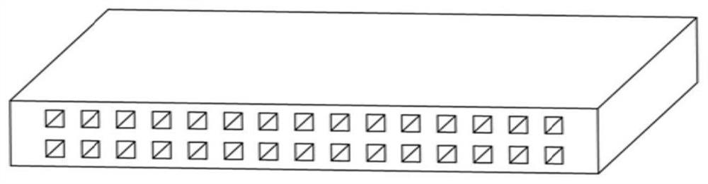
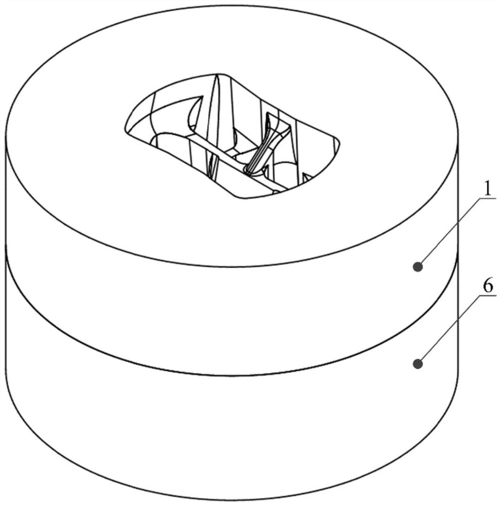
[0040] In a typical embodiment of the present invention, such as Figure 2 to Figure 12 As shown, a microchannel tube forming die is given.

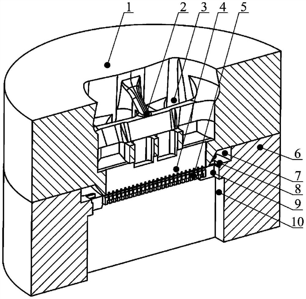
[0041] like figure 2 The microchannel tube forming die shown is used for extrusion forming of microchannel tubes, especially for extrusion forming of multi-row microchannel flat tubes in the refrigeration system, through the shunt channel 3 and welding chamber 7 through which the material flows. And the structural setting of the forming channel 9 solves the problems of high mold stress and unbalanced billet flow in the extrusion forming process of multi-row microchannel flat tubes, thereby achieving the effect of improving the quality of the workpiece and prolonging the life of the mold. The microchannel tube forming mold mainly includes a mold body, and the mold body can be an integrated mold, or can be such as figure 2 , image 3 The split mold shown in , can adopt the form of cooperation of the upper mold 1 and the lower mold 6; ...

Embodiment 2

[0064] In another typical embodiment of the present invention, such as Figure 2 to Figure 12 As shown, a microchannel tube forming method is provided, utilizing the microchannel tube forming die as in Example 1.

[0065] The microchannel tube forming method comprises the following steps:

[0066] Throw the blank into the feed channel and form multiple strands of material under the action of the split channel 3;

[0067] Part of the material enters the gap of the sub-mold core through the inner wall channel to form the inner wall of the workpiece; part of the blank is distributed around the mold core 5 through the outer wall channel to form the outer wall of the workpiece;

[0068] The inner wall of the workpiece and the outer wall of the workpiece are contact welded in the welding chamber 7, and the welded microchannel tube workpiece is output through the forming channel 9.

[0069] The set mold core neck 4 is combined with the welding chamber 7 to form an outer wall channe...


PUM


Abstract

The invention provides a micro-channel pipe forming die and method, and relates to the field of die forming, the micro-channel pipe forming die comprises a die main body, the die main body is provided with a feeding channel, a welding chamber and a forming channel which are communicated in sequence, multiple stages of shunting channels which are communicated in sequence are formed in the feeding channel, and a die core neck is arranged in the welding chamber; one end of the mold core neck is connected with a mold core composed of a series of sub-mold cores distributed in an array mode, the mold core stretches into the forming channel, an inner wall channel communicated with gaps of the sub-mold cores and the flow dividing channel is formed in the mold core neck, and an outer wall channel communicated with the flow dividing channel and the forming channel is formed between the mold core neck and the welding chamber; aiming at the problem that the quality requirement is difficult to meet when the micro-channel pipe is extruded and formed through a die at present, a multi-stage shunting channel is adopted to promote blank flowing so as to reduce the die stress, and meanwhile, flow guide channels are correspondingly arranged on the outer wall and the inner wall of the micro-channel pipe so as to promote the flowing uniformity of a deformation material and reduce the distortion of a profile; and the structural size of the formed micro-channel pipe is ensured to meet the precision requirement.

Description

technical field [0001] The invention relates to the field of mold forming, in particular to a microchannel tube forming mold and method. Background technique [0002] The heat dissipation components in traditional refrigeration systems have problems such as poor heat dissipation, short life and poor stability, making it difficult to manufacture products that meet energy efficiency standards. In recent years, microchannel tubes have gradually been used as heat dissipation elements to replace traditional heat dissipation elements in aerospace, lightweight vehicles, 3C electronics, and household appliances. The materials used in this microchannel tube are mostly non-ferrous metal materials such as aluminum, copper, magnesium and their alloys. Compared with traditional heat dissipation elements, microchannel tubes are small in size and high in heat dissipation efficiency, which can meet higher energy efficiency standards. The heat exchange medium can be water, oil, and coolant....

Claims


Application Information

Patent Timeline
Patent Type & Authority Applications(China)
IPC IPC(8): B21C25/02B21C23/08
CPCY02P40/57
Inventor 赵国群王跃林
Owner SHANDONG UNIV
Why Eureka
Try Eureka