
Method and device for protecting combustion chamber of internal combustion engine and improving combustion efficiency

A combustion efficiency and combustion chamber technology, applied in combustion air/combustion-air treatment, adding non-fuel substances to fuel, charging system, etc., can solve the problem of unsatisfactory fuel saving effect, poor carbon deposit removal effect, and reduced power performance. and other problems, to achieve the effect of improving fuel combustion efficiency, simple and reasonable structure, and reducing fuel consumption

Pending Publication Date: 2022-04-15
泉州市力丰机电科技有限公司
View PDF0 Cites 0 Cited by
  • Summary
  • Abstract
  • Description
  • Claims
  • Application Information

AI Technical Summary

Problems solved by technology

However, most of the currently used fuel additives have one or more of the following disadvantages: 1. The fuel additives have unsatisfactory effects on saving fuel and improving power, and some also reduce power performance. This is why the current fuel additives cannot be generally accepted by the majority of users Second, the fuel additive can not be combined with the fuel evenly and effectively when it is directly put into the fuel tank, making its effect unsatisfactory; Third, the fuel additive atomization and fuel atomization are mixed and transported to the combustion chamber, due to The fuel additive is diluted by the fuel so that carbon deposits will still be formed after the fuel is burned, only a small amount of carbon deposits are cleaned, and the carbon deposit removal effect is poor

Method used


Image

  • Method and device for protecting combustion chamber of internal combustion engine and improving combustion efficiency
  • Method and device for protecting combustion chamber of internal combustion engine and improving combustion efficiency

Examples


Embodiment Construction

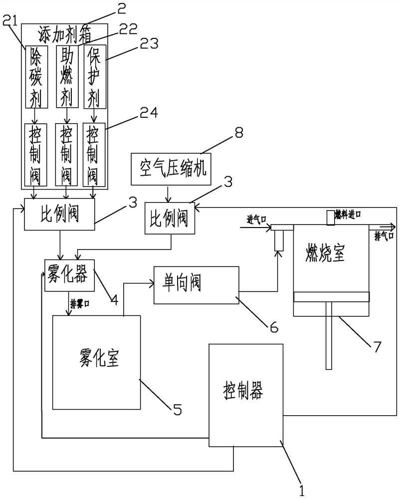
[0019] The present invention will now be further described in conjunction with the accompanying drawings and specific embodiments, wherein the controller, additive box, atomizer, air compressor, atomization chamber, proportional valve and check valve are all existing structural components, so in the description No specific structural description will be made, and the new design part will be described in detail in the following embodiments.

[0020] refer to figure 1 , the preferred device for protecting the combustion chamber of an internal combustion engine and improving combustion efficiency of the present invention includes a controller 1, an air compressor 8, three control valves 24, an additive box 2, an atomizer 4, an atomizing chamber 5, and two proportional valve 3 and one-way valve 6, the additive box 2 is divided into three units and the carbon remover 21, combustion accelerant 22 and protective agent 23 are respectively placed in the three units, and the decarburize...


PUM


Abstract

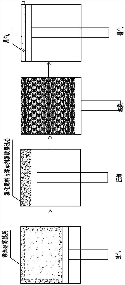
The invention relates to the technical field of energy conservation and emission reduction, and provides a method and device for protecting a combustion chamber of an internal combustion engine and improving combustion efficiency, and the method comprises the following steps: S1, arranging an air compressor, an additive box, an atomizer and an atomizing chamber on the internal combustion engine, and connecting the atomizer with an air inlet of the combustion chamber of the internal combustion engine through the atomizing chamber after atomization; s2, when the internal combustion engine starts to work, the atomization additive in the atomization chamber and air are pumped into the combustion chamber together, so that the atomization additive and the air are mixed and filled in the combustion chamber, an additive atomization layer is formed on the inner wall of the combustion chamber in the compression process, and then the additive atomization layer is mixed with fuel conveyed into the combustion chamber; clean protection of the combustion chamber and high-efficiency combustion of fuel are achieved. The problems that an existing additive added into an oil tank cannot be effectively utilized in the front stroke of an air cylinder and the effect of removing carbon deposition in a combustion chamber of an internal combustion engine is not ideal are solved.

Description

technical field [0001] The invention relates to the technical field of energy saving and emission reduction, in particular to a method and device for protecting a combustion chamber of an internal combustion engine and improving combustion efficiency. Background technique [0002] Energy saving and emission reduction is the top priority of energy shortage in today's world, and the combustion efficiency of fuel oil directly affects the effect of energy saving and emission reduction. Fuel additives can remove carbon deposits, improve oil quality, promote full combustion of fuel oil, improve combustion efficiency, and save fuel; Its atomization quality enables the fuel to be fully burned to reduce harmful gas emissions and achieve the purpose of energy saving and emission reduction. [0003] In the field of internal combustion engines, in order to improve fuel combustion efficiency, increase output power, reduce fuel consumption, remove carbon deposits and reduce harmful gas em...

Claims


Application Information

Patent Timeline
Patent Type & Authority Applications(China)
IPC IPC(8): F02B77/04F02M25/00F02M23/00F02M29/00
Inventor 黄伍桂
Owner 泉州市力丰机电科技有限公司
Learn More