An electronic fuse circuit with integrated anti-reverse current

A reverse current, anti-reverse technology, applied in the direction of adjusting electrical variables, instruments, control/regulating systems, etc., can solve the problems of consumption, large chip area, chip volume and cost increase, to avoid reverse current, chip Area and cost reduction, cost reduction effect

CN114356013BActive Publication Date: 2022-05-27江苏长晶科技股份有限公司
5 Cites 0 Cited by

Patent Information

Authority / Receiving Office
CN · China
Patent Type
Patents(China)
Current Assignee / Owner
Publication Date
2022-05-27

Smart Images

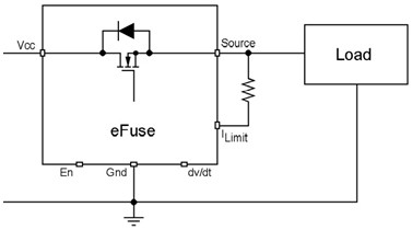
  • Figure 1
    Figure 1
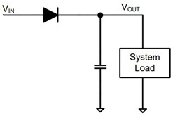
  • Figure 2
    Figure 2
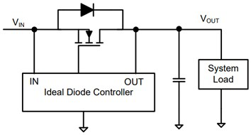
  • Figure 3
    Figure 3
Patent Text Reader

Abstract

An integrated anti-reverse current electronic fuse circuit, based on the traditional electronic fuse efuse circuit, includes PMOS transistors PS1, PS2, NMOS transistor NS and output power NMOS transistor Npower and is used to detect the power supply VIN voltage and output voltage VOUT The control circuit of the reverse current protection module, the reverse current protection module outputs control signals V+, V- and substrate potentials VS and VS2 to control PS1, PS2, NS switches and the substrate potentials of Npower, PS1 and PS2. The Npower substrate potential is switched to the lowest potential of the two, forming a body diode reverse bias to avoid reverse current.
Need to check novelty before this filing date? Find Prior Art

Description

technical field

[0001] The invention relates to a power management chip of an integrated circuit, in particular to an integrated electronic fuse circuit (efuse) for preventing reverse current. Background technique

[0002] As portable electronic products are widely used in all aspects of work and life, they put forward higher requirements on the performance of power supply. Modern electronic systems are designed with high integration to provide excellent performance and multiple functions. These systems use multi-voltage power distribution to support various types of power sources to ensure proper operation of the load. One of the main expectations is to minimize system downtime under any circumstances for transient abnormal events such as overload or short circuit conditions. For example, when a hot-swappable hard drive enters a storage system, the large inrush current can cause a voltage dip on the connecting bus and ultimately affect other operating loads on the same bus...

Examples

Embodiment Construction

[0026] see Figure 4 , in the electronic fuse efuse circuit diagram of the present invention to prevent reverse current, including the traditional electronic fuse efuse circuit part, wherein, VIN, VOUT, RILIM, EN, dV / dt, gnd are the ports of the chip, used to connect the external chip Components, chip internal function modules include charge pump, overvoltage protection module, enable module, undervoltage protection module, output slope control module, temperature protection module, current limiting protection module and gate controller. Figure 4 The dotted box marks the content of the present invention added on the basis of the prior art. The reverse current protection module is used to detect the VIN and VOUT signals, and output the substrate bias switching control signals V+ and V- of the power NMOS transistor Npower, as well as the substrate potentials VS and VS2. The PMOS transistors PS1 and PS2 are enhanced PMOS transistors, and the NMOS transistor NS is an enhanced is...