Efficient feeding transmission device suitable for stacking wafers

A kind of transmission device, high-efficiency technology, applied in the direction of transportation and packaging, sustainable manufacturing/processing, electrical components, etc., can solve the problems of unfavorable adsorption of different materials or wafers, inconvenient adjustment, small capacity of wafer cassettes, etc., to achieve The effect of reducing the risk of wafer drop, increasing work efficiency, and reducing labor intensity

Active Publication Date: 2022-04-15
三河建华高科有限责任公司
View PDF10 Cites 0 Cited by
  • Summary
  • Abstract
  • Description
  • Claims
  • Application Information

AI Technical Summary

Problems solved by technology

[0007] The purpose of the present invention is to provide a high-efficiency feeding transmission device suitable for stacking wafers, so as to solve the problem that the capacity of the wafer box proposed in the above-mentioned background technology is small, and manual loading is required during loading; at the same time, the vacuum suction head is used for a long time , the suction power drops, and it is not easy to replace; at the same time, it is not convenient to adjust the position of each vacuum suction head, which is not conducive to adsorption of different materials or wafer-related problems

Method used


Image

  • Efficient feeding transmission device suitable for stacking wafers
  • Efficient feeding transmission device suitable for stacking wafers
  • Efficient feeding transmission device suitable for stacking wafers

Examples


Embodiment 1

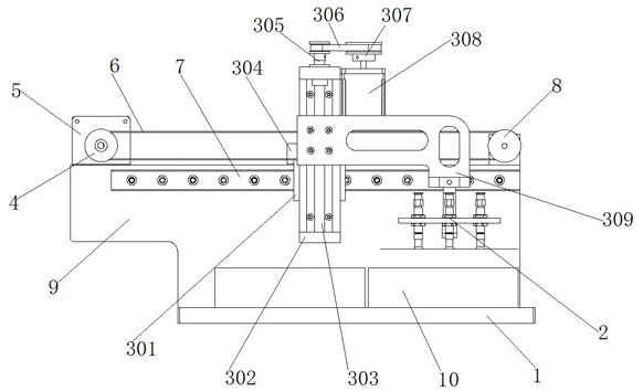
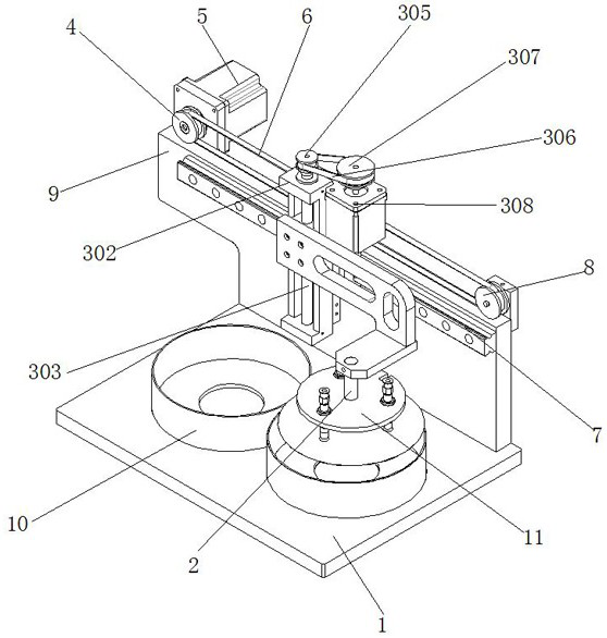
[0038] Example 1, such as Figure 1-4 As shown, the circular magazine 10 filled with wafers is placed above the bottom plate 1 of the magazine, and the second servo motor 5 drives the first synchronous tooth profile through the second driving pulley 4 and the second driven pulley 8. The belt 6 reciprocates horizontally, and the 匚-shaped plate 302 moves horizontally reciprocatingly through the timing belt splint 304 clamped on the first synchronous toothed belt 6 at the same time, and the sliding sleeve 301 on the 匚-shaped plate 302 guides and slides on the guide rail 7 , to ensure the stability and precision of the movement of the 匚-shaped plate 302, the first servo motor 308 works to drive the first driven pulley 305 and the first driving pulley 307 to rotate, and at this time drives the threaded rod 303 to perform forward and reverse rotation, so that the connection The arm 309 moves in the vertical direction, sucks the wafer inside the round magazine 10 through the three va...

Embodiment 2

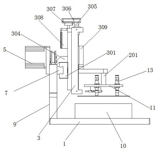
[0039] Example 2, such as Figure 5-6 As shown, when the vacuum suction head 13 needs to be replaced, the hinge block 204 is pushed at this time to make the two sets of second hinge rods 210 rotate to change positions, and then under the restriction of the limit rod 206, the two sets of L-shaped rods 207 are The horizontal direction is far away from each other. At this time, the vacuum suction head 13 can be unrestricted. At this time, the vacuum suction head 13 can be slid in the installation groove 12, and the vacuum suction head 13 can be replaced, and then the other vacuum suction head 13 can be replaced. The suction head 13 slides to the inside of the installation groove 12 and between the two sets of arc splints 208, under the elastic force of the spring 205, the hinge block 204 is reset, so that the two sets of arc splints 208 are close to each other to clamp the vacuum suction head 13 Live fixed.

[0040] Working principle: Place the round material box 10 full of wafe...


PUM


Abstract

The efficient feeding transmission device comprises a material box bottom plate, circular material boxes are arranged on the two sides of the top of the material box bottom plate, a mounting plate is arranged at one end of the back face of the top of the material box bottom plate, and a guide rail is arranged at the top of one end of the front face of the mounting plate; a vacuum material taking assembly is arranged on the outer side of the guide rail in a sliding mode, a connecting shaft is arranged at the bottom of the vacuum material taking assembly, the outer side of the connecting shaft is sleeved with an adjusting assembly, and a vacuum suction head mounting disc is arranged at the bottom of the connecting shaft. The capacity of two groups of circular material boxes fixed on the material box bottom plate is increased by eight times compared with that of a previous wafer box, more wafers can be stored, continuous manual material box replacement is reduced, the labor intensity is reduced, the connecting arm can reciprocate in the horizontal direction and the vertical direction through cooperation of all parts of the vacuum material taking assembly, and the working efficiency is improved. Transfer and feeding of wafers by the vacuum suction head can be realized, and the wafers can be conveyed to a working position.

Description

technical field [0001] The invention relates to the technical field of electrical parameter testing and classification of semiconductor discrete device GPP chips, in particular to a high-efficiency feeding transmission device suitable for stacking wafers. Background technique [0002] Wafer refers to the silicon wafer used to make silicon semiconductor circuits, and its raw material is silicon. High-purity polycrystalline silicon is dissolved and mixed with silicon crystal seeds, and then slowly pulled out to form cylindrical single crystal silicon. After the silicon ingot is ground, polished, and sliced, it forms a silicon wafer, that is, a wafer. Because the feeding end will be loaded and unloaded frequently, on the premise that the equipment layout meets the production process, the feeding end of the equipment and the working area There will be a certain distance between them, and a kind of equipment is needed to transport the materials. In the PSS process, for the load...

Claims


Application Information

Patent Timeline
Patent Type & Authority Applications(China)
IPC IPC(8): H01L21/677H01L21/683
CPCY02P70/50
Inventor 段成龙
Owner 三河建华高科有限责任公司
Why Eureka
Try Eureka