Sucker rod cleaning device

A technology for cleaning devices and sucker rods, applied in cleaning methods and tools, cleaning methods using liquids, cleaning methods using tools, etc., can solve the problems of sucker rod body corrosion, low work efficiency, and easy to be polluted, etc. Achieve the effect of quickly loosening dirt and avoiding inconvenience

Pending Publication Date: 2022-04-19
延安广晟石油工程有限公司
View PDF0 Cites 0 Cited by
  • Summary
  • Abstract
  • Description
  • Claims
  • Application Information

AI Technical Summary

Problems solved by technology

Due to frequent contact with oil and repeated movements, it is easy to be polluted. After long-term use, the sucker rod needs to be cleaned to avoid the residual mud, water, oil, etc. from corroding the sucker rod and affecting its use.
[0003] In the prior art, the sucker rod is generally cleaned by mixing hot water and steam mixed with chemicals. This cleaning can remove the oil and sludge on the surface of the sucker rod, but the chemical agents often have a negative effect on the sucker rod body. A certain amount of corrosion is produced. After several routine cleanings, the sucker rod body may also be rusted, and there will be dirt or other attachments on the surface that cannot be removed by conventional cleaning.
Some technicians will also use the steam cleaning method to heat and clean the sucker rods with special equipment such as a steam truck. This method requires a large investment in equipment, and the boiler consumes a lot of fuel, and the waste water containing wax and dirty oil is in the work site. Flowing around, causing pollution to the environment
[0004] When the attachment on the sucker rod cannot be cleaned by the above method, the mechanical cleaning method will be further used to remove the rust or other attachments that cannot be removed on the surface of the sucker rod with sandpaper or a grinder, and then make an anti-corrosion layer , this processing method has low working efficiency. When using a belt machine for mechanical grinding, both the sucker rod and the belt machine need to rotate, and one of the two is required to be able to move in the axial direction of the sucker rod. The whole working mechanism is relatively complicated
At the same time, mechanical cleaning often causes greater damage to the sucker rod, and generally requires grinding off a layer, and the grinding amount of different parts may vary, which may cause stress concentration, and make the overall sucker rod weakened strength

Method used


Image

  • Sucker rod cleaning device
  • Sucker rod cleaning device
  • Sucker rod cleaning device

Examples


Embodiment 1

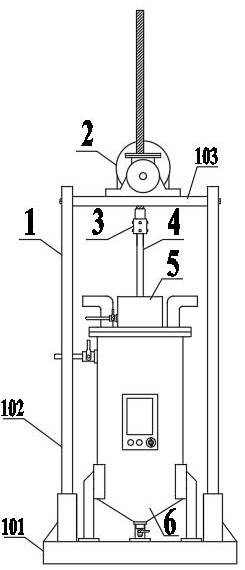
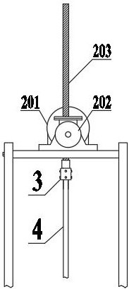
[0048] Such as figure 1 As shown, the sucker rod cleaning device includes a load-bearing frame 1, a screw lifter 2, a connecting device 3, a flushing device 5, and a heating device 6. In the figure, the load-bearing frame 1 is the main part, specifically composed of a base 101, two vertical plates 102 and horizontal plate 103 are formed, and two vertical plates 102 are oppositely arranged, and horizontal plate 103 is installed between two vertical plates 102, and the two ends of horizontal plate 103 are fastened by screw. figure 2 Among them, the lead screw lifter 2 is arranged on the top of the horizontal plate 103, the lead screw lifter 2 includes a motor 201, a transmission gear box 202 and a lead screw 203, the motor 201 drives the lead screw 203 to move up and down through the transmission gear box 202, and the transmission gear box 202 is In the existing structure, in the figure, the connecting device 3 is installed on the bottom of the lead screw 203 for fixing the suc...

Embodiment 2

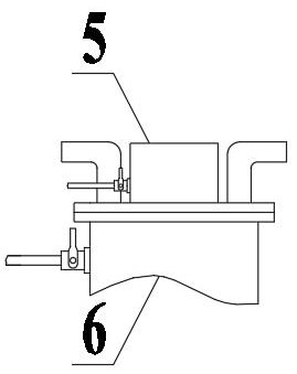
[0051] Such as Figure 4 As shown, the flushing device 5 includes a cavity 501 and a flange 502 located at the bottom of the cavity 501. The inner wall of the cavity 501 is provided with an annular high-pressure pipeline 503, and a plurality of high-pressure nozzles 504 are evenly distributed on the high-pressure pipeline 503, wherein : The high-pressure pipeline 503 includes a single-layer or multi-layer loop, and the high-pressure nozzles 504 on the loop are arranged in a staggered manner. Specifically, in this embodiment, two rows of high-pressure pipelines 503 are arranged in parallel. Specifically, the spraying directions of the high-pressure nozzles 504 all point to the central position, and the spraying angle can be horizontal or inclined downward by 5°-30°.

[0052] It should be noted that the flushing device 5 can also be equipped with a cover 505, and the cover 505 and the cavity 501 are connected by threads. Figure 5 Among them, the inner wall of the cover body 5...

Embodiment 3

[0055] Such as Figure 8 As shown, the heating device 6 includes a heating tank 601, a water inlet pipe 602, a sewage discharge pipe 603, an air inlet 604, an exhaust port 605 and a temperature control box 606, wherein: the water inlet pipe 602 is installed on the upper part of the side wall of the heating tank 601, and the sewage discharge The pipe 603 is installed at the bottom of the heating tank 601, and the liquid added can be clear water or cleaning liquid. The air inlet 604 and the exhaust port 605 are both arranged on the top of the heating tank 601, the air inlet 604 and the exhaust port 605 can be closed freely, and a fan is connected to discharge steam, and the temperature control box 606 is arranged on the side of the heating tank 601 For adjusting the temperature, the heating device 6 can adopt the prior art, and this embodiment is used to show the layout structure.


PUM


Abstract

The invention discloses a sucker rod cleaning device and belongs to the technical field of oil well equipment maintaining.The sucker rod cleaning device comprises a bearing frame, a lead screw lifting machine, a connecting device, a flushing device, a heating device and the like, a sucker rod is vertically hung through the lead screw lifting machine, so that oil dirt and dirty water in the cleaning process can be directionally collected under the gravity effect, and then the sucker rod is cleaned; inconvenience caused in the traditional horizontal cleaning process is avoided, the flushing device can automatically flush the sucker rod through a high-pressure pipeline and a high-pressure spray head, and surface oil dirt and oil sludge can be efficiently removed by further combining with a heating device. Compared with existing equipment, the sucker rod polishing device has the advantages of being high in automation degree, easy to operate, high in dirt-removing power and the like, and damage of a mechanical polishing method to a sucker rod body is avoided.

Description

technical field [0001] The invention belongs to the technical field of oil well equipment maintenance, in particular to a sucker rod cleaning device. Background technique [0002] In the field of petroleum machinery, the sucker rod is a frequently used device. Due to frequent contact with oil and repeated movements, it is easy to be polluted. After long-term use, the sucker rod needs to be cleaned to avoid the residual mud, water, oil, etc. from corroding the sucker rod and affecting its use. [0003] In the prior art, the sucker rod is generally cleaned by mixing hot water and steam mixed with chemicals. This cleaning can remove the oil and sludge on the surface of the sucker rod, but the chemical agents often have a negative effect on the sucker rod body. There will be a certain corrosion effect. After several routine cleanings, the sucker rod body may also be rusted, and there will be dirt or other attachments on the surface that cannot be removed by conventional cleanin...

Claims


Application Information

Patent Timeline
Patent Type & Authority Applications(China)
IPC IPC(8): B08B1/00B08B3/02B08B7/00B08B13/00
CPCB08B3/02B08B7/0071B08B1/002B08B13/00
Inventor 袁军学袁晓军刘忠涛王琦李刚韩香妮张静马惠云
Owner 延安广晟石油工程有限公司
Why Eureka
Try Eureka