
Double-zero foil blank 8079 alloy head and tail quality control method

A quality control method and double-zero foil technology, applied in manufacturing tools, furnaces, heat treatment equipment, etc., can solve problems such as scratches, and achieve the effects of improving quality, reducing production costs, and reducing rework loss and burnout

Pending Publication Date: 2022-04-19
贵州中铝铝业有限公司
View PDF5 Cites 0 Cited by
  • Summary
  • Abstract
  • Description
  • Claims
  • Application Information

AI Technical Summary

Problems solved by technology

[0005] The purpose of the present invention is to provide a method for controlling the quality of the head and tail of the double zero-foil blank 8079 alloy, so as to solve the problem that the bow-shaped part proposed in the above-mentioned background technology will expand outwards with the aluminum alloy coil of the outer ring, and the inner and outer rings of the aluminum alloy coil Relative motion between layers still exists, causing problems with scratch generation

Method used


Image

  • Double-zero foil blank 8079 alloy head and tail quality control method
  • Double-zero foil blank 8079 alloy head and tail quality control method
  • Double-zero foil blank 8079 alloy head and tail quality control method

Examples


specific Embodiment approach 1

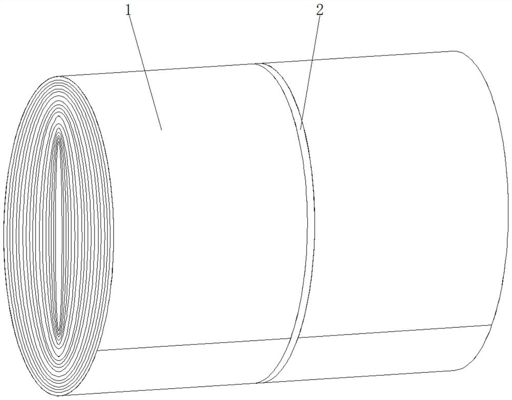
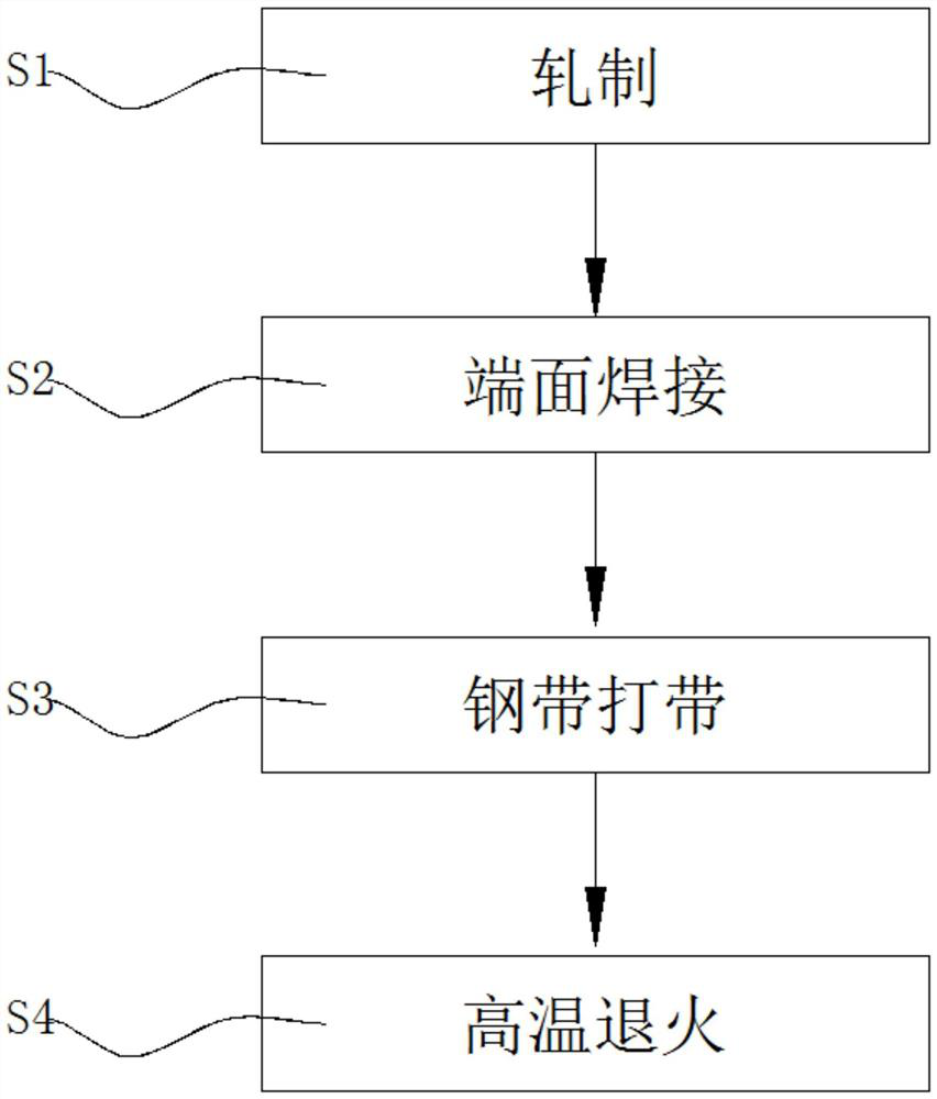
[0033] Specific implementation mode one: please refer to Figure 1-6 , the present invention provides a technical solution: a method for controlling the quality of the head and tail of a double zero-foil blank 8079 alloy, comprising the following steps:

[0034] S1, rolling the aluminum alloy material into a thin plate with a thickness of 7-4.0mm, and winding the thin plate to form an aluminum alloy material coil 1;

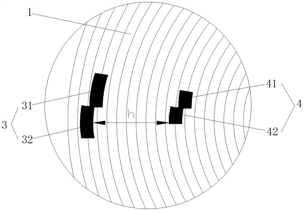
[0035] S2, spot welding the first electrode 3 and the second electrode 4 on the end surface of the aluminum alloy coil 1;

[0036] S3, making a steel strip 2 in the middle of the aluminum alloy coil 1;

[0037] S4, sending the aluminum alloy material roll 1 into an annealing furnace for high-temperature annealing treatment of finished products.

[0038] In step S1, when the aluminum alloy material coil 1 is finished, the aluminum alloy material coil 1 is supported by a trolley in advance. In step S2, the first welding rod 3 and the second welding rod 4 are clos...

specific Embodiment approach 2

[0040] Specific embodiment two: this embodiment is a further limitation of specific embodiment one, such as figure 2 As shown, the first welding rod 3 is made up of the first upper welding section 31 and the first lower welding section 32, the first upper welding section 31 and the first lower welding section 32 are mutually staggered, and the bottom end of the first upper welding section 31 is in line with the The top ends of the first lower welding section 32 are connected, and the welding sections connected in a staggered manner are arranged to avoid excessive weld seam of the aluminum alloy coil 1 and reduce the risk of tearing and breaking the strip during the next rolling pass.

specific Embodiment approach 3

[0041] Specific implementation mode three: this implementation mode is a further limitation of specific implementation mode two, such as figure 2 As shown, the second welding rod 4 is made up of the second upper welding section 41 and the second lower welding section 42, the second upper welding section 41 and the second lower welding section 42 are staggered from each other, and the bottom end of the second upper welding section 41 is in line with the The top ends of the second lower welding segments 42 are connected to each other.


PUM

PropertyMeasurementUnit
thicknessaaaaaaaaaa
lengthaaaaaaaaaa
lengthaaaaaaaaaa

Abstract

The invention discloses a double-zero foil blank 8079 alloy head and tail quality control method which comprises the following steps: S1, rolling an aluminum alloy material into a thin plate with the thickness of 7-4.0 mm, and rolling the thin plate to form an aluminum alloy coil; s2, a first welding rod and a second welding rod are welded to the end face of the aluminum alloy coil in a spot welding mode; s3, making a steel belt in the middle of the aluminum alloy coil; and S4, the aluminum alloy coil is fed into an annealing furnace for finished product high-temperature annealing treatment, in the step S1, when the aluminum alloy coil is ended, the aluminum alloy coil is jacked by a trolley in advance, and in the step S2, the first welding rod and the second welding rod are close to the outer ring of the aluminum alloy coil. According to the double-zero-foil blank 8079 alloy head and tail quality control method, an end face spot welding mode is adopted, welding spots can effectively restrain outer ring loose layers caused by thermal expansion in the annealing process of the material coil, the trolley is used for abutting against the aluminum alloy material coil so that the outer ring loose layers can be effectively prevented, and scratches caused by relative movement between the outer ring layer and the inner ring layer of the material coil can be effectively reduced through a steel belt.

Description

technical field [0001] The invention relates to the technical field related to aluminum processing technology, in particular to a method for controlling the quality of the head and tail of a double zero-foil blank 8079 alloy. Background technique [0002] Over the years, the scratches of the head and tail pine layers have been one of the important factors affecting the yield of the cold-rolled section. The yield of individual coils with serious scratches is low after removing defects, or the diameter of the coil is insufficient after removing defects, resulting in tape reels, especially When the 8079 alloy is produced with a large coil diameter, the head and tail scratches increase, and the yield is only 89.84%. [0003] The existing Chinese patent with the notification number CN113215384A proposes a protective tool for preventing the loose layer of the outer ring of the aluminum alloy coil, including a first bow, a second bow and a hinge connector, and the two ends of the f...

Claims


Application Information

Patent Timeline
Patent Type & Authority Applications(China)
IPC IPC(8): C22F1/04C21D9/52C21D1/26
CPCC22F1/04C21D9/52C21D1/26
Inventor 唐海荣王玉明苏佩雄游建敏
Owner 贵州中铝铝业有限公司
Learn More