Correction method and correction circuit of wireless transceiver

A wireless transceiver and receiving path technology, applied in electrical components, transmission systems, etc., can solve problems such as reducing the linearity of the base frequency circuit or the intermediate frequency circuit, increasing the base frequency circuit or the intermediate frequency circuit, and saturation of the base frequency circuit or the intermediate frequency circuit. , to achieve the effect of improving the flatness

Pending Publication Date: 2022-04-19
REALTEK SEMICON CORP
View PDF10 Cites 0 Cited by
  • Summary
  • Abstract
  • Description
  • Claims
  • Application Information

AI Technical Summary

Problems solved by technology

However, the base frequency circuit and the intermediate frequency circuit each have a set power upper limit, increasing the power of the base frequency circuit or the intermediate frequency circuit will reduce the linearity of the base frequency circuit or the intermediate frequency circuit, or even cause the base frequency circuit or the intermediate frequency circuit to saturate
Poor linearity or circuit saturation can degrade wireless transceiver performance

Method used


Image

  • Correction method and correction circuit of wireless transceiver
  • Correction method and correction circuit of wireless transceiver
  • Correction method and correction circuit of wireless transceiver

Examples


Embodiment Construction

[0015] The technical terms in the following explanations refer to the customary terms in this technical field. If some terms are explained or defined in this specification, the explanations of these terms shall be based on the descriptions or definitions in this specification.

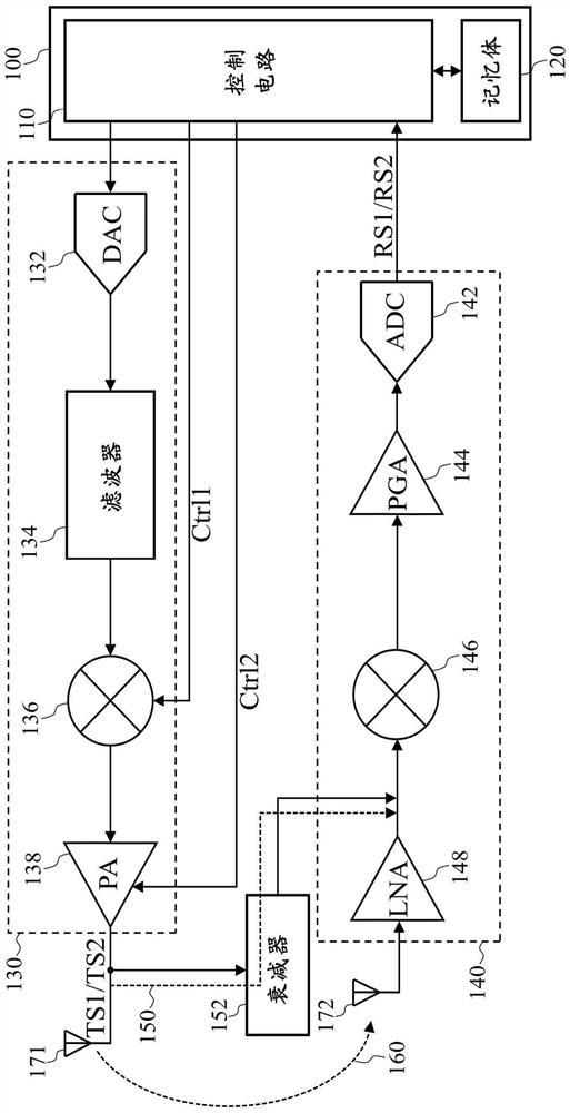
[0016] The disclosure of the present invention includes a calibration method and a calibration circuit for a wireless transceiver. Since some of the components included in the wireless transceiver of the present invention may be known components individually, the details of the known components will be omitted in the following description without affecting the full disclosure and implementability of the device invention . In addition, part or all of the process of the calibration method of the wireless transceiver of the present invention may be in the form of software and / or firmware, and may be executed by the calibration circuit of the wireless transceiver of the present invention or its equivalent ...


PUM


Abstract

The invention discloses a correction method and a correction circuit of a wireless transceiver. The wireless transceiver comprises a transmission path and a receiving path. The transmission path comprises a mixer. The correction method includes: (A) adjusting a first parameter of a first resonant circuit of the mixer; (B) receiving a first input signal through a coupling path and the receiving path; (C) measuring a first power of the first input signal; (D) repeating the steps (A) to (C) to obtain a plurality of first powers; and (E) finding out a first target parameter corresponding to the maximum one of the first powers.

Description

technical field [0001] The invention relates to a wireless transceiver, in particular to a correction method and a correction circuit for the wireless transceiver. Background technique [0002] A wireless transceiver can operate in multiple frequency bands, and a frequency band includes multiple channels. Wireless transceivers are usually designed to have the same output power for different channels of the same frequency band, ie, designed to have high flatness. [0003] In the design stage, the resonant circuit (LC tank circuit) of the RF circuit of the wireless transceiver needs to be optimally adjusted to set parameters (ie, inductance value and capacitance value), so that the frequency response of the RF circuit can have the best flatness. However, there are often process errors in mass production. If the process error exceeds the tolerance range of the parameters set during development, the flatness of the wireless transceiver will deteriorate. [0004] One of the co...

Claims


Application Information

Patent Timeline
Patent Type & Authority Applications(China)
IPC IPC(8): H04B1/40
CPCH04B1/40
Inventor 黃建融吕宜樺
Owner REALTEK SEMICON CORP
Why Eureka
Try Eureka