
Stable humidity generating device based on permeation tube

A humidity generation and permeation tube technology, applied in the direction of humidity control, instruments, control/regulation systems, etc., can solve the problems of poor pressure capacity, water accumulation in pipelines, short service life, etc., achieve constant temperature and increase mass transfer area effect

Active Publication Date: 2022-04-22
上海淳禧应用技术股份有限公司
View PDF13 Cites 0 Cited by
  • Summary
  • Abstract
  • Description
  • Claims
  • Application Information

AI Technical Summary

Problems solved by technology

[0004]At present, most of the existing humidity generators use the bubbling method for humidification, which is to pass the gas through an aqueous solution at a certain temperature to generate a gas with a certain humidity, but this The method is limited by the gas flow rate and the temperature of the aqueous solution, so it cannot generate moisture in a large range, and the humidity is not easy to control, and it is prone to condensation, causing problems such as water accumulation in the pipeline, which makes it unable to meet the needs of different working environments
[0005] provides a gas humidity generator in the patent CN202121679766.9, the gas humidity generator lacks the setting of the baffle plate in the humidification process, which will make the Ionized water cannot form turbulent flow and the heat transfer efficiency is low, so that the permeation tube cannot effectively humidify the air. In the existing gas humidity generating water tank, baffle plates are installed to form turbulent flow, but they are often arranged in a single or double bow shape. In the following Although the heat transfer efficiency is high when the single bow is set, its pressure capacity is poor, which will cause the problem of short service life. When the double bow is set, although the pressure capacity is good and the service life is long, the heat transfer efficiency is poor, which will cause The problem of uneven heating of liquids

Method used


Image

  • Stable humidity generating device based on permeation tube
  • Stable humidity generating device based on permeation tube
  • Stable humidity generating device based on permeation tube

Examples


Embodiment Construction

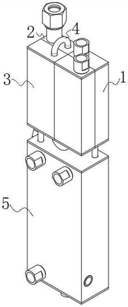
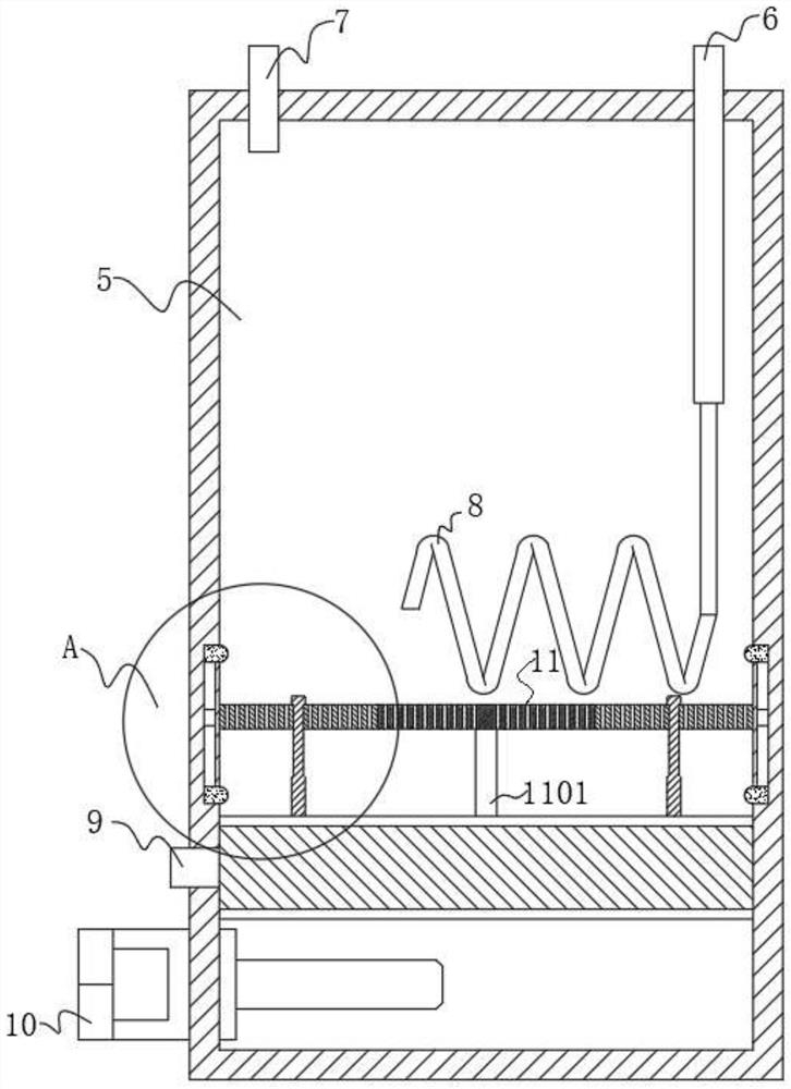
[0030] A stable humidity generating device based on a permeation tube, comprising a preheating box 1, a gas humidity measuring box 2, a gas mixing box 3 and a gas humidity generating water tank 5, the preheating box 1 is provided with two, and the two preheating boxes The hot box 1 is fixedly connected, the first connecting pipeline 4 is connected between the gas humidity measuring box 2 and the gas mixing box 3, and the gas humidity generating water tank 5 is arranged on the lower side of the preheating box 1, A fourth connecting pipeline 12 is connected between the preheating box 1 and the gas mixing box 3, and a second connecting pipeline 6 is connected between the preheating box 1 and the gas humidity generating water tank 5. A third connecting pipeline 7 is communicated between the gas mixing box 3 and the gas humidity generation water tank 5; a permeation pipe 8 is also included, and the permeation pipe 8 is arranged inside the gas humidity generation water tank 5, and th...


PUM


Abstract

The invention relates to the technical field of humidity generators, and discloses a stable humidity generating device based on a permeation tube, which comprises a gas humidity generating water tank, the permeation tube and a baffling device, the permeation pipe enters the gas humidity generation water tank in a U shape and is coiled on the lower side of the gas humidity generation water tank, and deionized water is stored outside the permeation pipe; the baffling device is fixedly arranged at the bottom of the inner side of the gas humidity generation water tank, the baffling device is arranged between the bottom of the inner wall of the gas humidity generation water tank and the permeation pipe, and when the temperatures of the upper part and the lower part in the gas humidity generation water tank tend to be the same, the baffling device is converted into a double-arch shape from a single arch shape; and when the temperature difference between the upper part and the lower part is too large, the baffling device is changed into a single arch from a double arch, so that the heat transfer efficiency is improved, and the temperature of the deionized water is rapidly and uniformly heated.

Description

technical field [0001] The invention relates to the technical field of humidity generators, in particular to a stable humidity generator based on permeation tubes. Background technique [0002] The measurement of humidity has been widely used in all walks of life. In the field of industrial environmental protection, humidity is an important parameter in flue gas monitoring, and in the CEMS system, the measured value of humidity participates in the conversion of pollutant emission concentration. Humidity measurement The accuracy is of great significance for the control of the total amount of pollutant discharge and environmental protection. [0003] The humidity monitoring in the CEMS system uses humidity probes of different principles to monitor the humidity of the flue gas in real time. With long-term use, the accuracy of the humidity probe measurement will cause measurement errors due to the interference of various factors. Therefore, it is necessary to regularly confirm ...

Claims


Application Information

Patent Timeline
IPC IPC(8): G05D22/02
CPCG05D22/02
Inventor 李峰王成海
Owner 上海淳禧应用技术股份有限公司
Learn More