Local anesthesia controllable spraying device for clinical anesthesia

A spray device and local anesthesia technology, which is applied in hypnosis devices, anesthesia equipment, nebulizers for treatment, etc., can solve the problems of single function and inability to accurately control the amount of sprayed medicine, and achieve the effect of improving the effect

Pending Publication Date: 2022-04-26
商丘市中心医院
View PDF0 Cites 0 Cited by
  • Summary
  • Abstract
  • Description
  • Claims
  • Application Information

AI Technical Summary

Problems solved by technology

[0004] Aiming at the defects and problems existing in the existing anesthesia spray device, the present invention provides a local anesthesia controllable spray device for clinical anesthesia. It also effectively solves the problem that the existing anesthesia spray device has a single function and cannot accurately control the amount of sprayed medicine.

Method used


Image

  • Local anesthesia controllable spraying device for clinical anesthesia
  • Local anesthesia controllable spraying device for clinical anesthesia
  • Local anesthesia controllable spraying device for clinical anesthesia

Examples


Embodiment 1

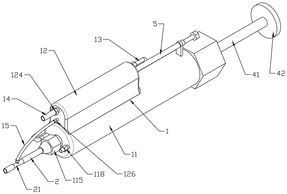
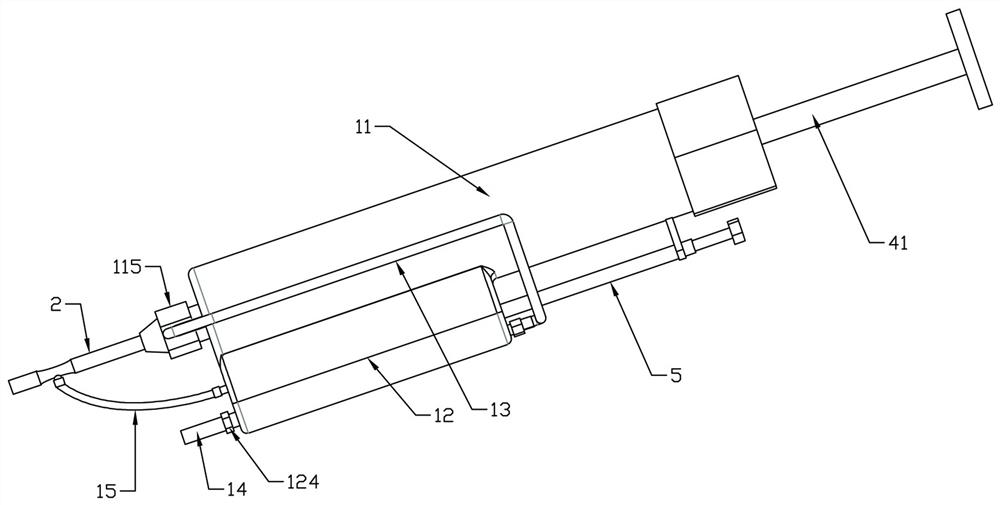
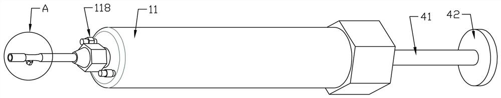
[0033] Topical anesthesia generally adopts the method of spray anesthesia, that is, the anesthetic is sprayed on the surface of the part to be anesthetized in the form of aerosol through the spray device, so that the skin can quickly absorb the anesthetic. The existing anesthesia spray has a simple structure and uses atmospheric pressure. The handle controls the push pump to push the gas into the anesthetic storage bottle, so that the gas pressure in the bottle increases. When the water nozzle is opened, the anesthetic will be forced out of the bottle by atmospheric pressure; but in actual use, the gas pushed into the anesthetic bottle It can only spray out the anesthetic agent in the anesthesia bottle. It has a single function and cannot accurately control the amount of drug sprayed according to the needs of the operation. During anesthesia, only the medical staff can roughly estimate the amount of sprayed drug. The accuracy is poor, and it is easy to cause excessive or sprayed...

Embodiment 2

[0053] The difference between embodiment 2 and embodiment 1 is that the outer wall of the auxiliary cylinder is axially provided with an observation window that can observe the inside of the drug storage chamber, and the observation window is provided with a scale, so as to facilitate precise adjustment of the depth of the control screw. .

Embodiment 3

[0055] The difference between Embodiment 3 and Embodiment 2 is that a throttling valve is provided on the linkage air pipe used to communicate the exhaust hole with the pressure regulating hole, and the throttle valve is used to adjust the flow rate of the inner channel of the linkage air pipe. There are many ways, for example: a throttle valve is installed on the exhaust hole, the other port of the throttle valve is connected to the linkage air pipe, and the other end of the linkage air pipe is connected to the pressure regulating hole, so that the linkage air pipe can be adjusted during use. According to the demand, the moving speed of quantitative piston linkage driving is controlled.


PUM


Abstract

The invention discloses a local anesthesia controllable spraying device for clinical anesthesia. The local anesthesia controllable spraying device comprises a spraying body, a jet flow medicine spraying pipe, a quantitative piston, a suction piston and a quantitative control assembly. A control cavity and a medicine storage cavity are horizontally arranged in the spray body at an interval, the control cavity and the medicine storage cavity are both columnar sealed cavities, and the tail end of the control cavity is communicated with the outside; the suction piston and the quantitative piston are installed in the control cavity and the medicine storage cavity in a matched mode respectively and can slide back and forth along the inner wall of the cavity in a sealed mode. The anesthetic spraying device is unique in structure and convenient to use, anesthetic can be quickly and uniformly sprayed to an affected part when the anesthetic spraying device is used, and the problems that an existing anesthetic spraying device is single in function, and the spraying dosage cannot be accurately controlled are effectively solved.

Description

technical field [0001] The invention belongs to the technical field of medical anesthesia equipment, in particular to a local anesthesia controllable spray device for clinical anesthesia. Background technique [0002] Local anesthesia, also known as local anesthesia, refers to the application of local anesthetics to parts of the body in a conscious state, so that the sensory nerve conduction function of a certain part of the body is temporarily blocked, and the motor nerve conduction remains intact or at the same time. blocked state. This block should be completely reversible without any tissue damage. The advantages of local anesthesia are simplicity, safety, awakeness of the patient, few complications, and little impact on the physiological function of the patient; common local anesthesia includes four types: topical anesthesia, local infiltration anesthesia, regional block, and nerve conduction block. [0003] The surface anesthesia generally adopts the method of spray ...

Claims


Application Information

Patent Timeline
IPC IPC(8): A61M19/00A61M11/00
CPCA61M19/00A61M11/007A61M2202/048A61M2202/0007
Inventor 李展
Owner 商丘市中心医院
Why Eureka
Try Eureka