
Emergency brake prevention type hydraulic disc brake

A disc brake, emergency brake technology, applied in the direction of brakes, brake types, bicycle brakes, etc., can solve the problems of potential safety hazards, the inability to install anti-lock braking systems, etc., and achieve the effect of reducing the flow rate and simple structure

Pending Publication Date: 2022-04-26
安徽欧利宝车业科技有限公司
View PDF7 Cites 1 Cited by
  • Summary
  • Abstract
  • Description
  • Claims
  • Application Information

AI Technical Summary

Problems solved by technology

[0003] Among the components of the hydraulic brake, the linkage oil pipe, as the hydraulic oil delivery element, needs to have the characteristics of high pressure resistance, impact resistance and wear resistance. , the ABS anti-lock braking system will be installed on the four-wheeled vehicle, but for the two-wheeled vehicle, the anti-lock braking system cannot be installed, and it is very easy to cause a safety hazard in the case of sudden braking.

Method used


Image

  • Emergency brake prevention type hydraulic disc brake
  • Emergency brake prevention type hydraulic disc brake
  • Emergency brake prevention type hydraulic disc brake

Examples


Embodiment 1

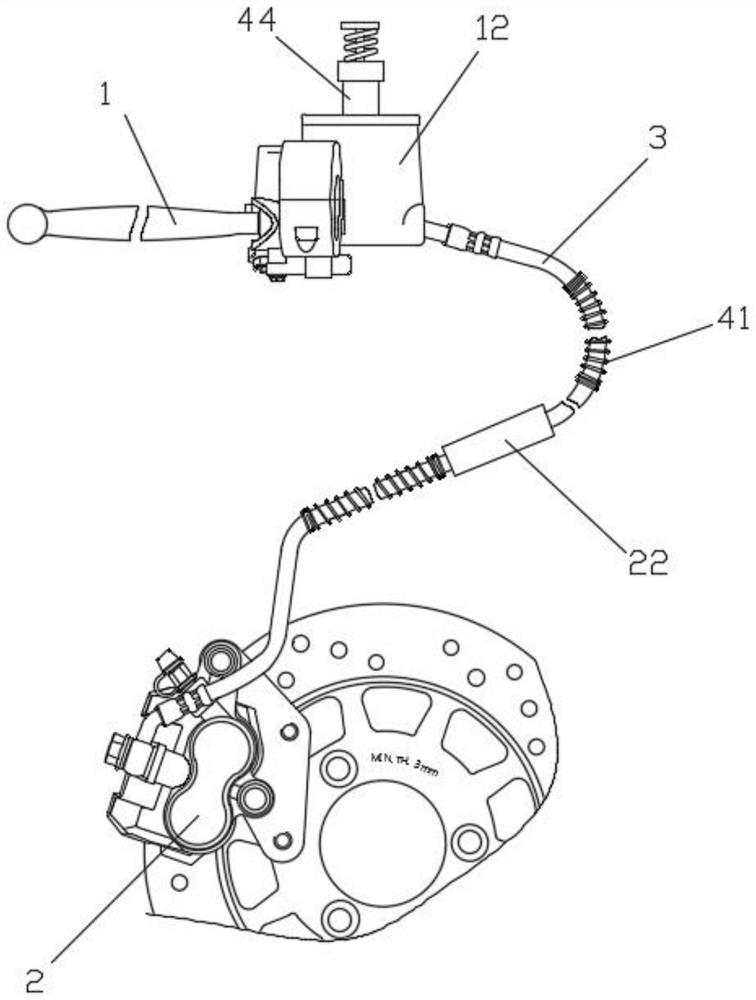
[0026] Such as Figure 1-2 As shown, an anti-sudden brake type hydraulic disc brake includes:

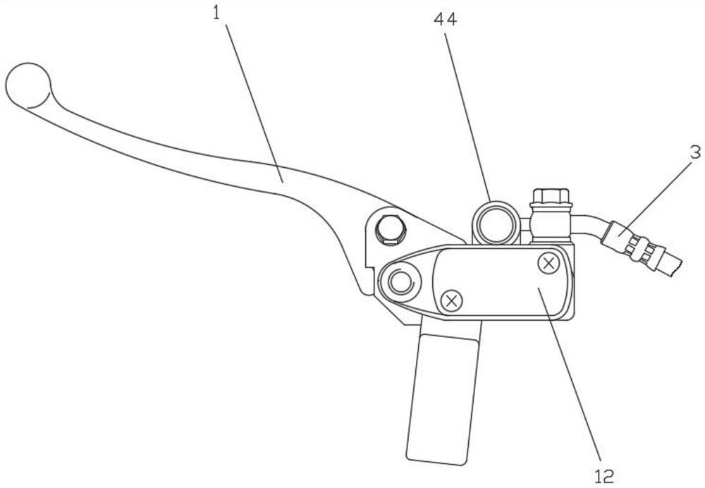
[0027] Handbrake 1, brake unit 2, linkage tubing 3;

[0028] The handbrake 1 is provided with a drive cylinder 12, and the drive cylinder 12 is connected to the brake unit 2 through a linkage oil pipe 3; the linkage oil pipe 3 includes a pipe body 21 and a buffer node 22;

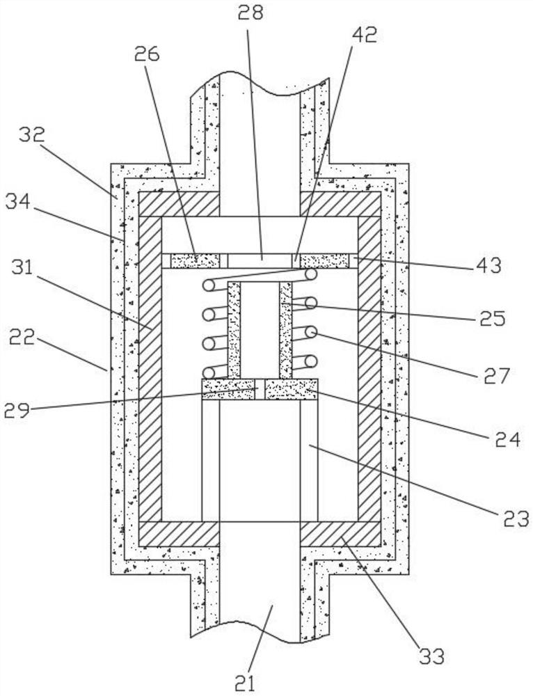
[0029] The buffer node 22 is connected to the pipe body 21, and the inside of the buffer node 22 is provided with a cavity, and a support guide post 23 is installed at the bottom of the cavity, a support plate 24 is fixed on the support guide post 23, and a sleeve 25 is fixed on the support plate 24, A floating plate 26 is slidably installed inside the cavity. A buffer spring 27 is provided between the floating plate 26 and the support plate 24. A perforation 28 is provided in the middle of the floating plate 26. When the floating plate 26 moves in the cavity, the sleeve 25 can be inserted into the perforation. ...

Embodiment 2

[0033] On the basis of Example 1, such as Figure 1-5 As shown, the buffer node 22 includes a cylinder liner 31 and an outer rubber layer 32, the two ends of the cylinder liner 31 are respectively equipped with connecting end caps 33, the support guide post 23 is fixed on one of the connecting end caps 33, and the outer rubber layer 32 is looped on the Outside the cylinder liner 31, a steel wire mesh 34 is embedded in the outer rubber layer 32.

[0034] A protective spring 41 is sheathed on the outside of the pipe body 21 .

[0035] An inner sealing rubber ring 42 is embedded inside the perforation 28 , and the inner sealing rubber ring 42 and the sleeve 25 are interference fit.

[0036] The outer ring of the floating plate 26 is surrounded by an outer sealing rubber ring 43 , and the outer sealing rubber ring 43 and the cylinder liner 31 are in an interference fit.

[0037] A display oil column 44 is installed on the handbrake 1, and the inside of the display oil column 44 ...


PUM


Abstract

An emergency brake prevention type hydraulic disc brake comprises a hand brake, a brake unit and a linkage oil pipe. When the braking force is large, the flow speed of hydraulic oil in the linkage oil pipe is increased, and when the hydraulic pressure with the large flow speed passes through the buffering node, the hydraulic oil impacts the floating plate, so that the buffering spring on the lower portion of the floating plate shrinks, and the floating plate moves downwards; when the flow speed of the hydraulic oil is slowed down, the floating plate is separated from the sleeve again under the action of the buffer spring, and the hydraulic oil can keep normal flow. By limiting the flow speed of hydraulic oil in the linkage oil pipe, the emergency braking condition of the vehicle during running is avoided, and the linkage oil pipe is suitable for braking of the two-wheeled vehicle.

Description

technical field [0001] The invention relates to the technical field of hydraulic brakes, in particular to an anti-emergency hydraulic disc brake. Background technique [0002] Hydraulic brakes, brakes are so-called brakes, and hydraulic brakes are brake devices that use hydraulic pressure as a driving force to control the brakes to work. It is a mechanical part that stops or slows down the moving parts in the machine. Commonly known as brakes, brakes. The brake is mainly composed of frame, brake parts and operating device. [0003] Among the components of the hydraulic brake, the linkage oil pipe, as the hydraulic oil delivery element, needs to have the characteristics of high pressure resistance, impact resistance and wear resistance. , The ABS anti-lock braking system will be installed on the four-wheeled vehicle, but for the two-wheeled vehicle, the anti-lock braking system cannot be installed, and it is very easy to cause a safety hazard under the situation of sudden ...

Claims


Application Information

Patent Timeline
Patent Type & Authority Applications(China)
IPC IPC(8): F16D65/14F16D65/097F15B21/00F16L55/027F16L55/05B62L3/02B60T7/08B60T13/14B60T17/04F16D55/00F16D121/04F16D125/02F16D125/08F16D125/16F16D127/00F16D129/02F16D131/00
CPCF16D65/14F16D65/0975F15B21/008F16L55/02718F16L55/05B62L3/023B60T7/08B60T13/148B60T17/04F16D2121/04F16D2125/02F16D2125/16F16D2125/08F16D2127/008F16D2129/02F16D2131/00F16D2055/0016
Inventor 张海波周振宇徐江涛
Owner 安徽欧利宝车业科技有限公司
Learn More