Continuous rotational flow falling film melt crystallizer

A technology of melting crystallizer and falling film, which is applied in crystallization separation, solution crystallization, chemical instruments and methods, etc., can solve the problems of poor crystal thickness uniformity, improve uniformity, slow down radial aggregation situation, and reduce energy consumption Effect

Pending Publication Date: 2022-04-29
SHANGHAI DONGGENG CHEM TECH CO LTD
View PDF0 Cites 0 Cited by
  • Summary
  • Abstract
  • Description
  • Claims
  • Application Information

AI Technical Summary

Problems solved by technology

[0005] In view of the above-mentioned shortcoming of the prior art, the object of the present invention is to provide a continuous swirl falling film melting crystallizer for solving the problem that the falling film melting crystallizer in the prior art has poor crystallization thickness uniformity during the crystallization process. The problem

Method used


Image

  • Continuous rotational flow falling film melt crystallizer
  • Continuous rotational flow falling film melt crystallizer
  • Continuous rotational flow falling film melt crystallizer

Examples


Embodiment 1

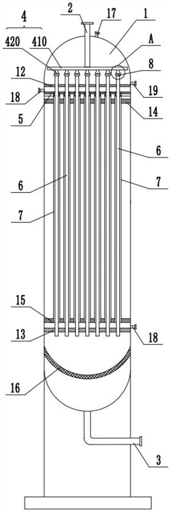
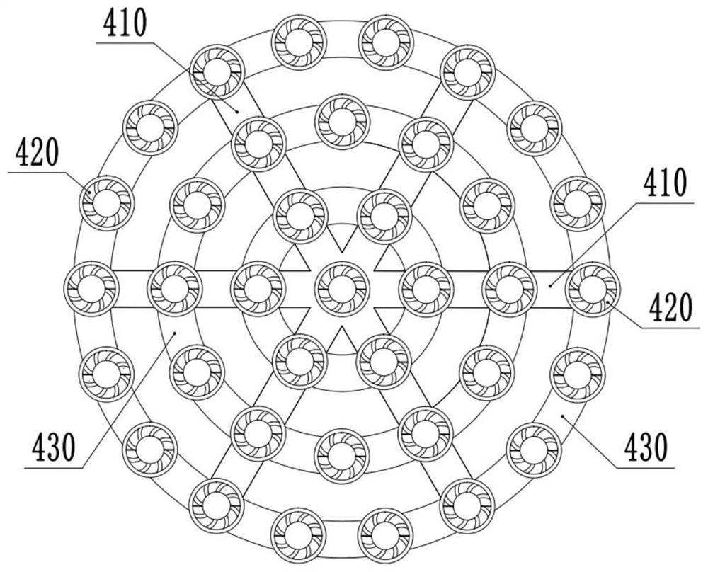
[0045] This embodiment is basically as figure 1 Shown: a continuous swirl falling film melting crystallizer, including a shell 1, a feed pipe 2 and a discharge pipe 3, the inside of the shell 1 is provided with a material distribution pipe network 4, and a cold and hot medium deflector 5 , some crystallization tubes 6 and some cold and heat medium tubes 7, combined figure 2 As shown, the material distribution pipe network 4 includes several material branch pipes 410 and several liquid separators 420, and the feed pipe 2 communicates with the material branch pipes 410. In this embodiment, the number of material branch pipes 410 is six, and the six material branch pipes 410 are close to each other. One end is connected, and this connection is also the connection between the material branch pipe 410 and the feed pipe 2 . Two adjacent material branch pipes 410 are also connected through arc-shaped pipes 430 . In this embodiment, three arc-shaped pipes 430 are designed between tw...

Embodiment 2

[0061] The only difference between this embodiment and Embodiment 1 is: Figure 12 As shown, in this embodiment, the inner diameter of the bottom of the straight pipe portion 820 gradually increases from top to bottom, that is, the longitudinal section of the inner wall of the bottom of the straight pipe portion 820 is in a figure-eight shape. In this embodiment, the inner diameter of the bottom of the straight pipe part 820 gradually increases from top to bottom. Compared with Embodiment 1, after the material forms a secondary swirl flow, it can stably transition to crystallization along the inner wall of the straight pipe part 820. On the inner wall of the tube 6, reduce the impact force on the inner wall of the crystallization tube 6 when the material enters the crystallization tube 6 from the straight tube portion 820, thereby better maintaining the swirl effect on the inner wall of the crystallization tube 6.

Embodiment 3

[0063] The only difference between this embodiment and Embodiment 1 is: Figure 13 As shown, in this embodiment, the bottom end of the liquid dispensing head 420 is located in the swirl part 810 , so as to prevent the material from splashing out of the swirl film distribution head 8 .


PUM


Abstract

The invention belongs to the field of crystallization equipment, and particularly discloses a continuous rotational flow falling film melt crystallizer which comprises a material distribution pipe network and a plurality of crystallization pipes, the material distribution pipe network comprises a plurality of liquid distribution heads, the top of each crystallization pipe is communicated with a rotational flow film distribution head, and a first spiral flow guide groove is formed in the inner wall of each rotational flow film distribution head; the rotational flow film distribution heads are in one-to-one correspondence with the liquid separation heads, and emptying channels are reserved between the rotational flow film distribution heads and the corresponding liquid separation heads. According to the invention, the rotational flow film distribution head can enable the material to enter the crystallization pipe in a rotational flow manner, so that the material has a circumferential initial speed and slows down the radial aggregation situation, and the emptying channel can be used for discharging air in the crystallization pipe and is more favorable for the material to form rotational flow, thereby further enabling the material to uniformly form a film on the wall of the crystallization pipe, enabling the crystallization to be more uniform, and improving the crystallization efficiency. The uniformity of crystal thickness is improved, and crystals are not easy to fall off; and the materials are distributed on the wall of the crystallization pipe in a rotational flow manner, so that the flow speed of the materials is increased, the crystallization time is effectively shortened, and the crystallization efficiency is improved.

Description

technical field [0001] The invention relates to the field of crystallization equipment, in particular to a continuous swirl falling film melting crystallizer. Background technique [0002] In the existing falling film crystallization equipment, a distributor is usually used to distribute the material or cold and hot media on the inner and outer walls of the crystallization tube, and the flow rate of the material or cold and hot media is controlled so that it flows downward in a film shape along the wall of the crystallization tube under the action of gravity . In order to maintain a good film-forming effect, the flow rate of materials or cooling and heating media is extremely slow, resulting in a long crystallization process and low crystallization efficiency. Moreover, since the crystallization tube is usually a round tube, the materials or cold and hot media will gather in a radial direction under the action of gravity, making the distribution of materials or cold and hot...

Claims


Application Information

Patent Timeline
Patent Type & Authority Applications(China)
IPC IPC(8): B01D9/02B01D29/03
CPCB01D9/00B01D29/035
Inventor 康小玲丁永良郑伯川郑晨李明全
Owner SHANGHAI DONGGENG CHEM TECH CO LTD
Why Eureka
Try Eureka