Eureka AIR delivers breakthrough ideas for toughest innovation challenges, trusted by R&D personnel around the world.

Enhanced deep nitrogen and phosphorus removal device and operation control method thereof

A technology for nitrogen and phosphorus removal and enhanced depth, applied in chemical instruments and methods, water pollutants, water/sludge/sewage treatment, etc. Nitrogen and phosphorus removal efficiency is not high, to achieve the effect of increasing denitrification and phosphorus release rate, reducing the cost of carbon source addition, and helping to maintain the effect

Pending Publication Date: 2022-04-29
HEILONGJIANG INST OF TECH
View PDF6 Cites 0 Cited by
  • Summary
  • Abstract
  • Description
  • Claims
  • Application Information

AI Technical Summary

Problems solved by technology

[0005] The present invention is in order to solve existing A 2 The / O process cannot make full use of the raw water carbon source, and the efficiency of nitrogen and phosphorus removal is not high, and due to incomplete denitrification, a large amount of nitrate nitrogen enters the anaerobic zone, causing the denitrification process to compete with the anaerobic phosphorus release process for limited carbon sources, which is not conducive to the formation of Strict anaerobic environment, which in turn affects anaerobic phosphorus release

Method used


Image

  • Enhanced deep nitrogen and phosphorus removal device and operation control method thereof

Examples


specific Embodiment approach 1

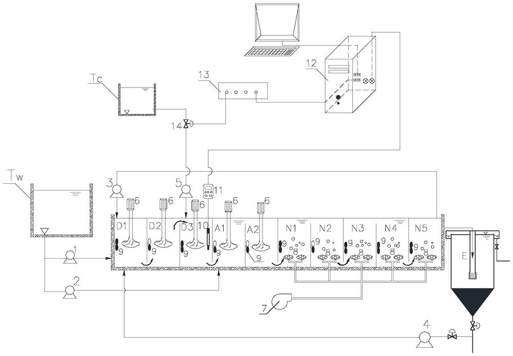
[0033] Specific implementation mode one: combine figure 1Describe this embodiment, this embodiment includes primary treatment water outlet structure Tw, main structure, first raw water pump 1, second raw water pump 2, internal circulation pump 3, sludge return pump 4, carbon source delivery pump 5, agitator 6. Blower 7, aeration device 8, water flow propeller 9, ORP online sensor 10, ORP host 11, electronic computer 12, PLC control system 13, electric valve 14, secondary sedimentation tank E and carbon source storage tank Tc; main body From left to right in the structure are anoxic first zone D1, anoxic second zone D2, anoxic transition zone D3, anaerobic first zone A1, anaerobic second zone A2, aerobic first zone N1, aerobic second zone N2, Aerobic zone 3 N3, aerobic zone 4 N4 and aerobic zone 5 N5; the first raw water pump 1 supplies the water in the primary treatment effluent structure Tw to the anoxic zone 1 D1, and the second raw water pump 2 supplies the water in the pri...

specific Embodiment approach 2

[0035] Specific implementation mode two: combination figure 1 Describe this embodiment, the first anoxic zone D1, the second anoxic zone D2, the anoxic transition zone D3, the first anaerobic zone A1, the second anaerobic zone A2, the first aerobic zone N1, and the second aerobic zone N2 in this embodiment The volumes of the respective reaction zones of the third aerobic zone N3, the fourth aerobic zone N4 and the fifth aerobic zone N5 are equal. This setting ensures that the system can provide a total water retention time for different water qualities, which is convenient for volume design, and ensures that the discharge of ammonia nitrogen can meet the standard discharge at lower temperatures, thereby achieving the purpose of deep nitrogen and phosphorus removal. Other structures and compositions are the same as those in Embodiment 1.

specific Embodiment approach 3

[0036] Specific implementation mode three: combination figure 1 To illustrate this embodiment, the total volume of the anoxic zone in this embodiment: the anoxic transition zone D3: the total volume of the anaerobic zone: the total volume of the aerobic zone = 2:1:2:5;

[0037] Wherein, the total volume of the anoxic zone=the volume of the first hypoxic zone D1+the volume of the second hypoxic zone D2,

[0038] The total volume of the anaerobic zone = the volume of the first anaerobic zone A1 + the volume of the second anaerobic zone A2;

[0039] The total volume of the aerobic zone = the volume of the first aerobic zone N1 + the volume of the second aerobic zone N2 + the volume of the third aerobic zone N3 + the volume of the fourth aerobic zone N4 + the volume of the fifth aerobic zone N5. Such setting ensures that the system can be designed according to the volume of different water qualities, and ensures that at lower temperatures, it is convenient to implement different ...


PUM


Abstract

The invention discloses an enhanced deep nitrogen and phosphorus removal device and an operation control method thereof, and relates to a nitrogen and phosphorus removal device and a control method thereof. The problems that in the prior art, the nitrogen and phosphorus removal efficiency is not high, a strict anaerobic environment is not formed easily due to incomplete denitrification, and then anaerobic phosphorus release is affected are solved. The device consists of an anoxic zone, an anoxic transition zone, an anaerobic zone and an aerobic zone, adopts two-point water feeding, and is provided with internal circulation and sludge backflow facilities. The anoxic zone is arranged in front of the anaerobic zone, and water is fed into the anoxic zone, so that a raw water carbon source can be fully utilized for denitrification, and the nitrogen removal efficiency is improved. The anoxic transition area is arranged behind the anoxic area, and carbon source feeding control is performed on the anoxic transition area, so that the concentration of nitrate nitrogen can be further reduced, the negative influence of the nitrate nitrogen on anaerobic phosphorus release is reduced, the phosphorus release rate is improved, and meanwhile, due to implementation of ORP on-line carbon source feeding control, the carbon source feeding amount can be minimized. The method is used for deep denitrification of domestic sewage and nitrogenous industrial wastewater.

Description

technical field [0001] The invention relates to a device for deep denitrification and dephosphorization of urban sewage and its operation control method, in particular to an anoxic / anaerobic / aerobic process enhanced deep denitrification and dephosphorization device and its operation control method, belonging to the technical field Theories, technologies and methods for the advanced treatment of sewage. It is suitable for the deep nitrogen and phosphorus removal treatment of urban domestic sewage. Background technique [0002] At present, urban sewage treatment plants operating in China generally suffer from the problem of low nitrogen and phosphorus removal efficiency, and more than half of them cannot meet the first-class A discharge standard stipulated in the national sewage discharge standard (GB18918-2002). However, most urban sewage has a low C / N ratio, and the carbon source in the biological denitrification process is far from sufficient. For small town sewage treatm...

Claims


Application Information

Patent Timeline
Patent Type & Authority Applications(China)
IPC IPC(8): C02F3/30C02F101/16
CPCC02F3/302C02F3/308C02F3/006C02F2301/08C02F2101/163C02F2209/005
Inventor 王伟王明刚张鑫刘丽娜代莹梁涛张敏
Owner HEILONGJIANG INST OF TECH
Why Eureka
Eureka Blog
Learn More