Joint detection device for NCVM vacuum coating product

A joint detection and vacuum coating technology, applied in the direction of measuring devices, instruments, etc., can solve the problems of complex processing process, high processing technology, increased production cost, etc., and achieve the effect of improving detection efficiency, reducing labor intensity, and increasing the degree of automation

Pending Publication Date: 2022-04-29
苏州市彩衣真空科技有限公司
0 Cites 0 Cited by

AI-Extracted Technical Summary

Problems solved by technology

Its processing technology is higher than ordinary vacuum plating, and its processing process is much more complicated than ordinary process
[0003] When performing a series of inspections on NVCM coating products, such as light transmission inspection, elect...

Method used

As shown in Figure 5 and Figure 6, control water pump 44 to start by intelligent control panel 45, water pump 44 will be pumped into water inlet pipe 34 by first flexible pipe by water pump 44 in the water storage tank 43, enters in the water inlet pipe 34 The water will flow into the upper pipe 32 and the lower pipe 33 respectively under the guidance of the connecting pipe 40, and as the water in the upper pipe 32 continues to increase, the sealing plug 35 will move downward, and then drive the positive electrode generator 29 downward. Move until the positive electrode generator 29 is in contact with the upper surface of the product to be detected, and as the water in the lower pipe 33 continues to increase, the floating block 36 will continuously move upward, and then the negative electrode receiver 30 will move upward until the negative electrode receives The device 30 is in contact with the lower surface of the product to be tested. When the positive generator 29 and the negative receiver 30 are in contact with the product to be tested, the water inlet pipe 34 is also accompanied by the entry of water, and the excess water will enter the pressure relief assembly. Excluded, the movement of the positive generator 29 and the negative receiver 30 is realized by water pressure, which can effectively maintain the working state of the positive generator 29 and the negative receiver 30, and improve the accuracy of the detection results. The through hole on the block 36, the drain hole 41 and the L-shaped outlet pipe 42 fixed in the drain hole 41 are offered on the lower pipeline 33 side walls, and the vertical pipe of the L-shaped outlet pipe 42 passes through the through hole and is connected with the through hole. Sliding fit, excess water will enter the L-shaped outlet pipe 42 under the action of water pressure, and then enter the second hose through the L-shaped outlet pipe 42, and finally flow into the water storage tank 43 to realize water recycling. , when the positive generator 29 and the negative receiver 30 are in contact with the product to be tested, the e...

Abstract

The invention discloses a joint detection device for NCVM vacuum coating products, and the joint detection device comprises a workbench, and also comprises a conveying device arranged on the workbench, a visible light detection device arranged on the workbench, and an electric breakdown detection device arranged on the workbench, and one end of the workbench is provided with a manipulator with a classification function. A plurality of connecting rods are arranged on the conveying device, and positioning frames are fixed to the ends, away from the conveying device, of the connecting rods. Joint detection of the detection device is realized, the production cost is reduced, the detection efficiency is improved, carrying and classification of products are all mechanically operated, and the labor intensity of workers is reduced.

Application Domain

Measurement devices

Technology Topic

Electric breakdownLight detection +4

Image

  • Joint detection device for NCVM vacuum coating product
  • Joint detection device for NCVM vacuum coating product
  • Joint detection device for NCVM vacuum coating product

Examples

  • Experimental program(1)

Example Embodiment

[0027] In order to enable those skilled in the art to better understand the solution of the present application, the technical solution in the embodiment of the application will be clearly and completely described below in conjunction with the accompanying drawings in the embodiment of the application. Obviously, the described embodiment is only It is an embodiment of a part of the application, but not all of the embodiments. Based on the embodiments in this application, all other embodiments obtained by persons of ordinary skill in the art without creative efforts shall fall within the scope of protection of this application.
[0028] It should be noted that the terms "first" and "second" in the description and claims of the present application and the above drawings are used to distinguish similar objects, but not necessarily used to describe a specific sequence or sequence. It should be understood that the data so used may be interchanged under appropriate circumstances for the embodiments of the application described herein. Furthermore, the terms "comprising" and "having", as well as any variations thereof, are intended to cover a non-exclusive inclusion, for example, a process, method, system, product or device comprising a sequence of steps or elements is not necessarily limited to the expressly listed instead, may include other steps or elements not explicitly listed or inherent to the process, method, product or apparatus.
[0029] In this application, the terms "upper", "lower", "left", "right", "front", "rear", "top", "bottom", "inner", "outer", "middle", The orientations or positional relationships indicated by "vertical", "horizontal", "horizontal", and "longitudinal" are based on the orientations or positional relationships shown in the drawings. These terms are mainly used to better describe the present invention and its embodiments, and are not intended to limit that the indicated device, element or component must have a specific orientation, or be constructed and operated in a specific orientation.
[0030] Moreover, some of the above terms may be used to indicate other meanings besides orientation or positional relationship, for example, the term "upper" may also be used to indicate a certain attachment relationship or connection relationship in some cases. Those skilled in the art can understand the specific meanings of these terms in the present invention according to specific situations.
[0031] Furthermore, the terms "installed", "disposed", "provided", "connected", "connected", "socketed" are to be interpreted broadly. For example, it may be a fixed connection, a detachable connection, or an integral structure; it may be a mechanical connection or an electrical connection; it may be a direct connection or an indirect connection through an intermediary; internal connectivity. Those of ordinary skill in the art can understand the specific meanings of the above terms in the present invention according to specific situations.
[0032] It should be noted that, in the case of no conflict, the embodiments in the present application and the features in the embodiments can be combined with each other. The present application will be described in detail below with reference to the accompanying drawings and embodiments.
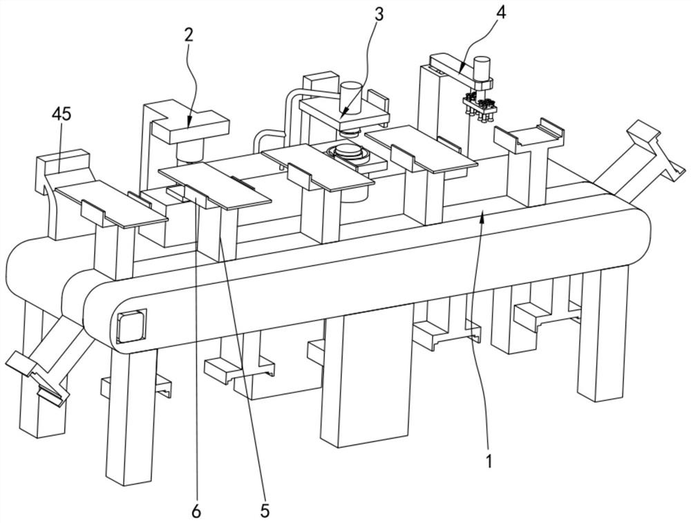
[0033] like figure 1 As shown, a combined detection device for NCVM vacuum coating products includes a workbench, and also includes a conveying device 1 arranged on the workbench, a visible light detection device 2 arranged on the workbench and an electric sensor arranged on the workbench. Breakdown detection device 3 , one end of the workbench is provided with a manipulator 4 with a classification function, a plurality of connecting rods 5 are provided on the conveying device 1 and a positioning frame 6 is fixed at the end of the connecting rods 5 away from the conveying device 1 .
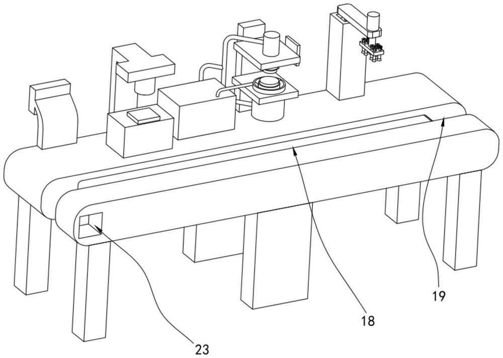
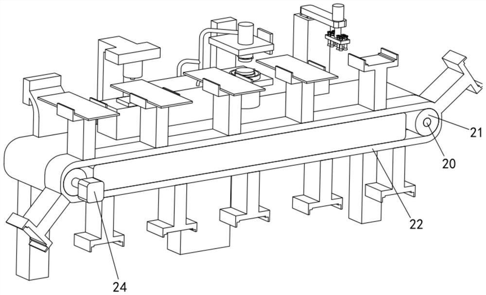
[0034] like figure 2 and image 3As shown, when in use, the staff will place the product to be tested on the positioning frame 6, and the positioning frame 6 will move along with the start of the transmission device 1. The transmission device 1 includes a movable channel 18 opened on the workbench And the installation groove 19 that is offered at the two ends of the workbench, the rotation shaft 20 is arranged in the installation groove 19, the roller 21 is sleeved on the rotation shaft 20, the conveyor belt 22 is arranged in the movable groove and the outer surface of the conveyor belt 22 and the roller 21 fit together, the conveyor belt 22 is fixedly connected with the connecting rod 5, and one side of the workbench is provided with a motor slot 23, a drive motor 24 is arranged in the motor slot 23 and the output shaft of the drive motor 24 is fixedly connected with the rotating shaft 20 on one side, and the workbench is provided with The intelligent control panel 45 can control the running state of the drive motor 24 through the intelligent control panel 45, start the drive motor 24 through the intelligent control panel 45, the output shaft of the drive motor 24 rotates, drives the rotating shaft 20 to rotate, and then drives the roller 21 to rotate, Under the cooperation of the rollers 21 and the conveyor belt 22, the conveyor belt 22 starts to move, and the movement of the conveyor belt 22 will move with the connecting rod 5, thereby realizing the movement of the positioning frame 6. With the movement of the positioning frame 6, the products to be detected enter first. Go to the visible light detection device 2 to detect the light transmittance.
[0035] like Figure 4 As shown, the visible light detection device 2 includes a mounting column 25 fixed on the workbench, a visible light emitter 26 fixed on the end of the mounting column 25 away from the workbench and a visible light receiver 27 fixed on the workbench, the visible light emitter 26 A strong light will be emitted to irradiate the product to be detected, and the light penetrating the product to be detected is collected and analyzed through the visible light receiver 27, and the analyzed data is transmitted to the intelligent control panel 45, and the product to be detected passes through the visible light detection device 2 After the detection, with the cooperation of the transmission device 1, it enters the electrical breakdown detection device 3 for detection.
[0036] like Figure 5 As shown, the electrical breakdown detection device 3 includes a fixed column 28 fixed on the workbench, a liquid extraction device arranged on the fixed column 28, and a positive electrode generator 29 and a negative electrode receiver 30 arranged on the liquid extraction device. The positive generator 29 and the negative generator used are the positive generator 29 and the negative receiver 30 of the electrical insulation strength tester of Beijing Zhonghang Dingli Instrument Equipment Co., Ltd., the model is LJC-50KV, and the positive generator 29 and the AC electrode column The negative electrode receiver 30 is connected to the negative electrode column, and then the voltage and other values ​​are set. The detection method of the electrical breakdown detection device 3 needs to place the product to be detected on the negative electrode receiver 30, and the positive electrode generator 29 Place it on the top of the product, then power on for detection, and the product to be detected enters between the positive generator 29 and the negative receiver 30 along with the movement of the conveyor belt 22, and then the positive generator 29 and the negative receiver 30 are in the liquid extraction device. With cooperation, the above state is achieved, that is, the lower end surface of the product to be tested is attached to the upper end surface of the negative receiver 30, and the lower end surface of the positive generator 29 is attached to the upper end surface of the product to be tested.
[0037] like Figure 5 , Image 6 and Figure 7 As shown, the liquid extraction device comprises a parallel frame 31 fixed on the fixed column 28, an upper pipeline 32 and a lower pipeline 33 arranged on the parallel frame 31, a connecting pipe 40 communicated with the upper pipeline 32 and the lower pipeline 33 and arranged on The water inlet pipe 34 on the connection pipe 40, the upper pipe 32 is provided with a sealing plug 35, the lower pipe 33 is provided with a floating block 36, and the sealing plug 35 is provided with a first fixed rod 37, and the fixed rod is fixed to the positive electrode generator 29. connection, the floating block 36 is fixed with a second fixed rod 38, the second fixed rod 38 is fixedly connected with the negative receiver 30, the floating block 36 is provided with a pressure relief assembly, and the parallel frame 31 is fixed with a scanner 39. The bottom side of 28 is fixed with a water storage tank 43, the water storage tank 43 is connected with the water inlet pipe 34 through the first hose, and the first hose is provided with a water pump 44, and the water pump 44 is fixed on the side wall of the water storage tank 43 , one end of the L-shaped water outlet pipe 42 communicates with the water storage tank 43 through a second flexible pipe.
[0038] like Figure 5 and Image 6 As shown, through the intelligent control panel 45 to control the start of the water pump 44, the water pump 44 will pump the water in the water storage tank 43 into the water inlet pipe 34 through the first flexible pipe, and the water entering the water inlet pipe 34 will be guided by the connecting pipe 40. Under the action, it flows into the upper pipeline 32 and the lower pipeline 33 respectively, and as the water in the upper pipeline 32 continues to increase, the sealing plug 35 will move downward, and then drive the positive generator 29 to move downward until the positive generator 29 and the waiting The upper surface of the product to be detected is in contact with each other, and as the water in the lower pipe 33 continues to increase, the floating block 36 will continuously move upwards, and then the negative receiver 30 will move upward until the negative receiver 30 is in contact with the lower surface of the product to be detected. Contact, when the positive electrode generator 29 and the negative electrode receiver 30 are in contact with the product to be tested, the water inlet pipe 34 is also accompanied by the entry of water, and the excess water will enter the pressure relief assembly to be discharged, and the positive electrode will be generated by water pressure. The movement of the device 29 and the negative receiver 30 can effectively keep the working state of the positive generator 29 and the negative receiver 30, and improve the accuracy of the detection results. The drain hole 41 on the side wall of the lower pipe 33 and the L-shaped outlet pipe 42 fixed in the drain hole 41, the vertical pipe of the L-shaped outlet pipe 42 passes through the through hole and is slidably matched with the through hole, and excess water will be in the Under the action of water pressure, it enters the L-shaped water outlet pipe 42, and then enters the second hose through the L-shaped water outlet pipe 42, and finally flows into the water storage tank 43 to realize water recycling. When the positive electrode generator 29 and the negative electrode receive After the devices 30 are in contact with the product to be tested, the positive generator 29 and the negative receiver 30 are used to conduct an electrical breakdown test on the product to be tested. Moving forward, the product after the detection is in the moving process, passes through the scanner 39, the scanner adopts the principle of optical machine vision intelligent detection, this type of scanner 39 can detect the defects on the surface of the object, defects such as stains, scratches, etc. traces, submerged pits, etc., the detected results are fed back to the intelligent control panel 45, and then the intelligent control panel 45 analyzes the detected results, and then transmits the analyzed results to the manipulator 4, and the manipulator 4 performs the inspection on the finished product. Classified storage, if there are unqualified products in the visible light detection and electric breakdown detection, the products of this type are stored in the collection tray marked with unqualified products through the manipulator 4, and the qualified products are stored in the collection tray marked with qualified products.
[0039] like Figure 8 and Figure 9 As shown, the manipulator 4 includes a support column 7 fixed on the workbench, a rotary motor 8 fixed on the support column 7 and a support plate 9 fixedly connected to the output shaft of the rotary motor 8, and the end of the support plate 9 away from the rotary motor 8 is fixed There is a first cylinder 10, a mounting plate 11 is fixed on the telescopic rod of the first cylinder 10, a suction cup assembly 12 is arranged on the mounting plate 11, an intelligent control panel 45 controls the rotation of the rotating motor 8, and then the supporting plate 9 and the rotating motor 8 are realized. The output shaft moves in an arc with the center of the circle. When the mounting plate is above the product, the rotating motor 8 stops, and then the telescopic rod of the first cylinder 10 is extended. With the extension of the first telescopic rod, the mounting plate 11 moves downward. , and then the suction cup assembly 12 also moves downward until the suction cup assembly 12 is in contact with the upper surface of the product. 14. The middle part of the lifting rod 13 is provided with a vent hole 15 connected with the vacuum suction cup 14. The outside of the lifting rod 13 is provided with a first spring 16, and the outside of the lifting rod 13 is also provided with a conflicting block 17. The first spring 16 The two ends of the two sides are respectively in contact with the collision block 17 and the mounting plate 11. With the downward movement of the mounting plate 11, the vacuum suction cup 14 will be in contact with the surface of the product. Due to the sliding fit between the lifting rod 13 and the mounting plate 11, When the vacuum chuck 14 is in contact with the upper surface of the product, it can play a buffering effect. When the lifting rod 13 moves upward, the first spring 16 is in a relaxed state, and then the cooperation between the collision block 17, the first spring 16 and the mounting plate 11 Next, the downward force of the vacuum chuck 14 is given to ensure the contact between the vacuum chuck 14 and the product. The air hole 15 is connected to the air pump, and the air pump will draw out the gas in the air hole 15 to form a negative pressure. Under cooperation, the product is sucked by the vacuum suction cup 14, and then the telescopic rod of the first cylinder 10 shrinks, and the product will be separated from the positioning frame 6 at this time, and under the cooperation of the rotating motor 8, the first cylinder 10 and the vacuum suction cup 14 , place the product in a suitable collection tray to complete the collection, and then the first spring 16 shrinks until it returns to its original state. At this time, the lifting rod 13 will also return to its original state for the next use. Due to multiple lifting There is a sliding fit between the rod 13 and the mounting plate 11 , and the vacuum chuck 14 can also absorb a variety of products with different shapes, thereby improving the scope of use of the vacuum chuck 14 .
[0040] The device realizes the movement of the product to be inspected through the cooperation of the conveying device 1 and the positioning frame 6, and then sends the product to be inspected into the corresponding inspection device in sequence, thereby improving the efficiency of inspection and effectively improving the efficiency of personnel during the inspection process. Safety: By setting the visible light detection device 2 and the electrical breakdown detection device 3 on the same workbench, the combination of visible light detection and electrical breakdown detection is realized, avoiding the inconvenience of a single detection, and reducing the production cost to a certain extent ; The detected products are classified by the manipulator 4, which effectively reduces the labor intensity of manual classification; during the detection process, the detection can be completed by the setting of the intelligent control panel 45, which greatly realizes the intelligence of the detection and reduces the The labor intensity of the staff is reduced, and continuous detection can be carried out to improve the detection efficiency.
[0041] The above descriptions are only preferred embodiments of the present application, and are not intended to limit the present application. For those skilled in the art, there may be various modifications and changes in the present application. Any modifications, equivalent replacements, improvements, etc. made within the spirit and principles of this application shall be included within the protection scope of this application.

PUM

no PUM

Description & Claims & Application Information

We can also present the details of the Description, Claims and Application information to help users get a comprehensive understanding of the technical details of the patent, such as background art, summary of invention, brief description of drawings, description of embodiments, and other original content. On the other hand, users can also determine the specific scope of protection of the technology through the list of claims; as well as understand the changes in the life cycle of the technology with the presentation of the patent timeline. Login to view more.

Similar technology patents

Spot welding system of air-conditioner backboard robot

ActiveCN104874907AMeet production takt requirementsReduce labor intensity
Owner:SHANGHAI XINSHEN METALWORK

Double-feedback mechanical arm automatic loading and unloading system and method

InactiveCN106826817AGuaranteed precision and efficiencyReduce labor intensity
Owner:河北省自动化研究所有限公司

Full-automatic watering vehicle

Owner:QINGDAO LANNONGGU AGRI PROD RES & DEV

Filtering, cleaning, drying three-in-one device

InactiveCN101455918AReduce labor intensity
Owner:WUXI ZHANGHUA MEDICAL EQUIP

Classification and recommendation of technical efficacy words

  • Reduce testing costs
  • Reduce labor intensity

Intelligent toilet

Owner:BEIJING ANSAIBO TECH

Machine vision based real-time diagnosis method and system of vegetable leaf diseases

ActiveCN102334422Areal-time diagnosisReduce testing costs
Owner:INST OF VEGETABLE & FLOWERS CHINESE ACAD OF AGRI SCI

Method for preparing gold-phase section samples aiming at embedded printed-circuit board

InactiveCN103698152AEnsure Stability and ConsistencyReduce testing costs
Owner:UNIV OF ELECTRONIC SCI & TECH OF CHINA

Method for intelligent automatic identification of transmission circuit parts

Owner:INFORMATION COMM COMPANY STATE GRID SHANDONG ELECTRIC POWER +2

City regional railway signal system and control method thereof

Owner:CHINA RAILWAY SIYUAN SURVEY & DESIGN GRP

Railway bearing intelligent on-line detection method and its device

InactiveCN101290265AReduce labor intensity
Owner:洛阳铭昊测控科技有限公司
Why Eureka
Try Eureka