Supercharge Your Innovation With Domain-Expert AI Agents!

Audio signal encoder, audio signal decoder, and method for encoding and decoding audio signal

An audio signal coding, audio signal technology, applied in speech analysis, code conversion, image communication, etc.

Inactive Publication Date: 2004-03-31
PANASONIC CORP
View PDF0 Cites 0 Cited by
  • Summary
  • Abstract
  • Description
  • Claims
  • Application Information

AI Technical Summary

Problems solved by technology

[0007] However, according to the above situation, in the prior audio signal encoding device and decoding device, in order to obtain good sound quality, it is necessary to encode and decode with a fixed amount of information, which cannot obtain high-quality sound quality with a high compression rate.

Method used


Image

  • Audio signal encoder, audio signal decoder, and method for encoding and decoding audio signal
  • Audio signal encoder, audio signal decoder, and method for encoding and decoding audio signal
  • Audio signal encoder, audio signal decoder, and method for encoding and decoding audio signal

Examples


Embodiment 1

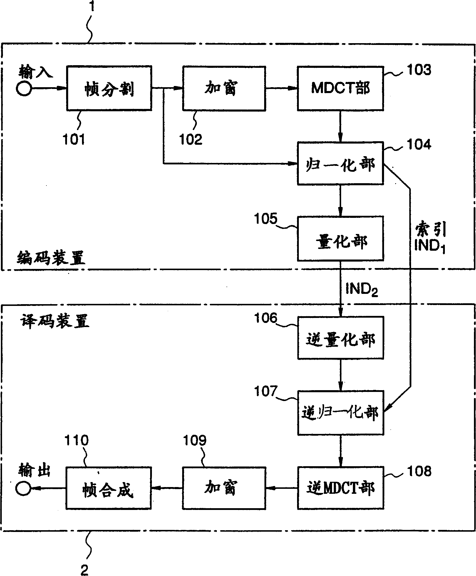
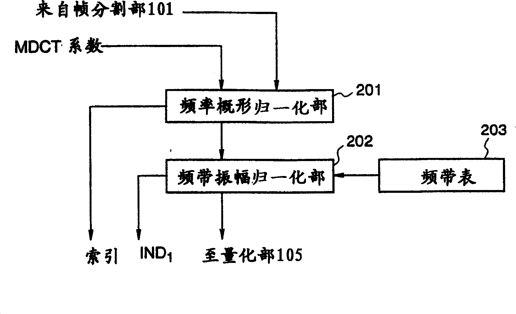
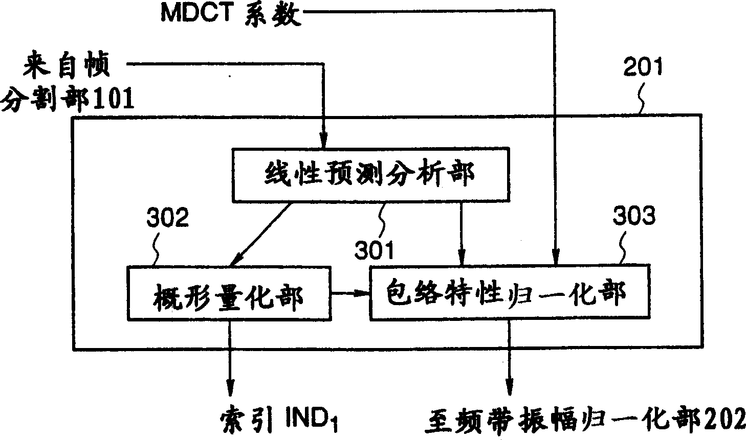
[0077] figure 1 It is a diagram showing the overall configuration of an audio signal coding device and a decoding device according to Embodiment 1 of the present invention. exist figure 1Among them, 1 is an encoding device, and 2 is a decoding device. In the encoding device 1, 101 is a frame division unit that divides the input signal into predetermined frame values, 102 is a windowing unit that multiplies the input signal by a window function on the time axis, and 103 is a modified discrete cosine transform (Modified Discrete Cosine Transform). The MDCT part of discrete cosine transform), 104 is a normalization part that takes the output of the frame division part 101, that is, the signal of the time axis, and the output of the MDCT part 103, that is, the MDCT coefficient, and performs normalization processing on the MDCT coefficient, 105 It is a quantization unit that takes the normalized MDCT coefficients as input and performs quantization processing. Here, a case wher...

Embodiment 2

[0122] Next, use Figure 5 An audio signal encoding device according to Embodiment 2 of the present invention will be described. In the second embodiment, only the structure of the quantization unit 105 of the encoding device 1 is different from the first embodiment, so only the structure of the quantization unit will be described here. exist Figure 5 Among them, 501 is the first small quantization unit, 502 is the second small quantization unit, and 503 is the third small quantization unit. The difference from the structure of the first embodiment above is that the first small quantization unit 501 divides the input MDCT coefficients into three frequency bands (high frequency, intermediate frequency, and low frequency) and performs quantization independently. The band quantization unit corresponds to a so-called "segmented vector quantizer". Usually, when using the vector quantization method for quantization processing, several elements can be extracted from the input MDC...

Embodiment 3

[0126] Next, use Figure 6 An audio signal encoding device according to the third embodiment will be described. In the third embodiment, only the structure of the quantization unit 105 of the encoding device 1 is different from the first embodiment, so only the structure of the quantization unit will be described here. exist Figure 6 Among them, 601 is a first small quantization unit, 602 is a first quantization band selection unit, 603 is a second small quantization unit, 604 is a second quantization band selection unit, and 605 is a third small quantization unit. The difference from the structure of the second embodiment above is that a first quantization band selection unit 602 and a second quantization band selection unit 604 are added.

[0127] Next, the operation thereof will be described. In the above-mentioned first quantization band selection unit 602 , the quantization error output of the first small quantization unit 601 is used to calculate which band of MDCT c...


PUM


Abstract

With respect to audio signal coding and decoding apparatuses, there is provided a coding apparatus that enables a decoding apparatus to reproduce an audio signal even through it does not use all of data from the coding apparatus, and a decoding apparatus corresponding to the coding apparatus. A quantization unit constituting a coding apparatus 1 comprises: a first sub-quantization unit 501 comprising sub-quantization units for low-band, intermediate-band, and high-band; a second sub-quantization unit 502 for quantizing quantization errors from the first sub-quantization unit 501; and a third sub-quantization unit 503 for quantizing quantization errors which have been processed by the first sub-quantization unit 501 and the second sub-quantization unit 502.

Description

technical field [0001] The present invention relates to an audio signal encoding device for encoding audio signals such as voice signals and music signals. In particular, a device that converts an audio signal from a time domain to a frequency domain by using methods such as orthogonal transformation, and can efficiently encode the transformed signal that can be expressed with as few code strings as possible than the source audio signal, and use A decoding device capable of decoding a high-quality and wide-band audio signal for all code strings or a part of code strings such as encoded signals, and a method for encoding and decoding the audio signal. Background technique [0002] Various methods have been proposed for efficiently encoding and decoding audio signals. For audio signals having a frequency band of 20 KHz or higher, such as music signals, in particular, the MPEG audio system and the like have been introduced in recent years. The encoding method represented by t...

Claims


Application Information

Patent Timeline
IPC IPC(8): G10L19/00G10L19/02G10L19/038H03M7/30H04B1/66H04B14/04
CPCH04B14/04H03M7/30G10L19/00G10L19/02H04B1/66H03M7/3082G10L19/038G10L19/0212H04N21/439
Inventor 津岛峰生则松武志石川智一
Owner PANASONIC CORP
Features
  • R&D
  • Intellectual Property
  • Life Sciences
  • Materials
  • Tech Scout
  • Unparalleled Data Quality
  • Higher Quality Content
  • 60% Fewer Hallucinations
Learn More