
Permanent magnet generator for offshore wind power and working method thereof

A permanent magnet generator and offshore wind power technology, applied in the direction of electrical components, electromechanical devices, electric components, etc., can solve the problems of reducing wind power generation efficiency, difficulty in maintenance and repair, and adding electric equipment, so as to avoid downtime accidents and maintenance needs , avoid ionization and electric corrosion, reduce the effect of weight

Pending Publication Date: 2022-04-29
CRRC WIND POWER(SHANDONG) CO LTD
View PDF0 Cites 0 Cited by
  • Summary
  • Abstract
  • Description
  • Claims
  • Application Information

AI Technical Summary

Problems solved by technology

[0004] 1. Water jacket cooling, air-to-air cooling and direct air cooling are all used on a large scale on land. The maintenance of generators on land is relatively convenient, but for offshore wind power generation, there are great difficulties in maintenance and repair;
[0005] 2. Water jacket cooling, air-to-air cooling and direct air cooling all require additional power sources, such as electric motors for forced cooling, which not only increases maintenance difficulties, but also increases electric equipment and reduces the efficiency of wind power generation

Method used


Image

  • Permanent magnet generator for offshore wind power and working method thereof
  • Permanent magnet generator for offshore wind power and working method thereof

Examples


Embodiment 1

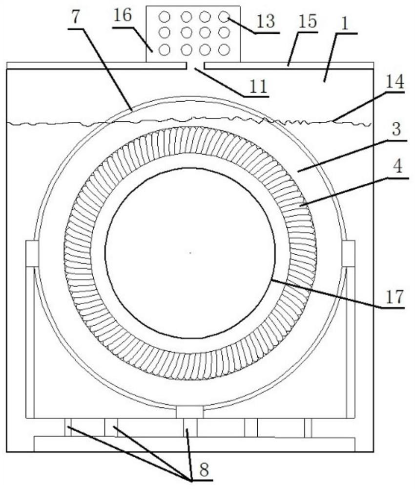
[0036] Such as figure 1 As shown, this embodiment provides a permanent magnet generator for offshore wind power, including at least a stator and a rotor 2, and a cooling cavity;

[0037] The rotor 2 is located outside the cooling cavity, and the stator is located inside the cooling cavity; the inside of the cooling cavity is filled with a cooling medium 18;

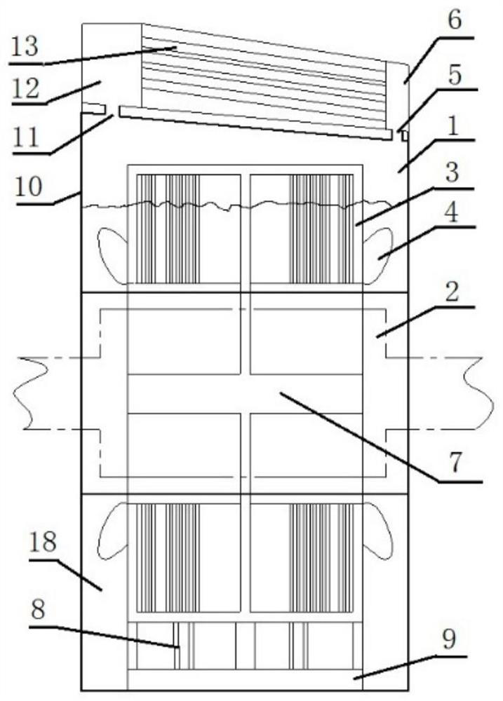
[0038] In this embodiment, the cooling cavity can be set as a glass fiber reinforced plastic cavity; figure 1 with figure 2 As shown, the FRP cavity 1 is composed of a cavity FRP 10 and an inner cavity FRP 17 to form a closed cooling cavity except the outlet 11 and the inlet 5 .

[0039] In this example, if figure 1 As shown, the stator includes a stator core 3, and one end of the stator core 3 is connected to a generator frame 9; the generator frame 9 is located inside the cooling cavity and is soaked in the cooling medium 18 Inside; the elastic connection between the stator core 3 and the generator base 9 can be re...

Embodiment 2

[0050] This embodiment further illustrates the permanent magnet generator for offshore wind power in Embodiment 1; specifically:

[0051] The stator core 3 and the stator coil form a whole, which are embedded in a steel cage 7 welded by steel pipes to form the stator of the generator. The stator has no stator casing, which not only reduces the weight of the stator, but also facilitates the heat dissipation of the stator core and the coil; the whole The stator core, stator coil and stator cage 7 are welded to the generator frame through the elastic support made of steel pipes, which can effectively reduce the high-frequency vibration generated during the operation of the generator and transmit it to the frame, so as to avoid damage to the glass fiber reinforced plastic cavity under the frame. Underseat damage.

[0052] The whole stator core 3, stator coil, stator cage 7 and generator base 9 form a whole and are placed in an airtight structure made of glass fiber reinforced plas...


PUM


Abstract

The invention provides a permanent magnet generator for offshore wind power and a working method thereof. The permanent magnet generator at least comprises a stator, a rotor and a cooling cavity, the rotor is located outside the cooling cavity, and the stator is located inside the cooling cavity; the cooling cavity is filled with a cooling medium; according to the invention, the whole stator is soaked in the cooling medium, so that maintenance-free or maintenance-frequency-reduced operation of the offshore unit is realized; the cooling device is suitable for cooling offshore wind turbines.

Description

technical field [0001] The invention belongs to the technical field of generator stator cooling, and in particular relates to a permanent magnet generator for offshore wind power and a working method thereof. Background technique [0002] A wind turbine is a power device that converts wind energy into mechanical work, which drives the rotor to rotate, and finally outputs alternating current; wind turbines generally include a wind wheel, a generator (including devices), a steering device (tail), a tower, a limiter, and a wind turbine. Wind turbines generally adopt water jacket cooling, air-to-air cooling and direct air cooling. [0003] The inventors have found that the existing wind turbine cooling methods have the following disadvantages: [0004] 1. Water jacket cooling, air-to-air cooling and direct air cooling are all used on a large scale on land. The maintenance of generators on land is relatively convenient, but for offshore wind power generation, there are great dif...

Claims


Application Information

Patent Timeline
IPC IPC(8): H02K9/197H02K9/20H02K9/22
CPCH02K9/197H02K9/20H02K9/225
Inventor 赵磊荆中金狄振峰苗云涛吴永鹏
Owner CRRC WIND POWER(SHANDONG) CO LTD
Features
  • Generate Ideas
  • Intellectual Property
  • Life Sciences
  • Materials
  • Tech Scout
  • Unparalleled Data Quality
  • Higher Quality Content
  • 60% Fewer Hallucinations
Learn More