Oil temperature control mechanism, refrigerating system, air conditioner and oil temperature control method

A technology of oil temperature control and refrigeration system, applied in the field of oil temperature control and oil temperature control mechanism, can solve the problems of high lubricating oil temperature and insufficient cooling of lubricating oil.

Pending Publication Date: 2022-05-03
GREE ELECTRIC APPLIANCES INC OF ZHUHAI
View PDF0 Cites 0 Cited by
  • Summary
  • Abstract
  • Description
  • Claims
  • Application Information

AI Technical Summary

Problems solved by technology

[0005] One of the objectives of the present invention is to propose an oil temperature control mechanism and an oil temperature control method, which solves the problem that in the prior art, the compressor operates under low load conditions, and the lubricating oil cannot be cooled well, and the lubricating oil is discharged from the compressor and enters the Technical problem of too high temperature of lubricating oil in oil separator

Method used


Image

  • Oil temperature control mechanism, refrigerating system, air conditioner and oil temperature control method
  • Oil temperature control mechanism, refrigerating system, air conditioner and oil temperature control method
  • Oil temperature control mechanism, refrigerating system, air conditioner and oil temperature control method

Examples


Embodiment 1

[0040] The embodiment describes the oil temperature control mechanism of the invention in detail.

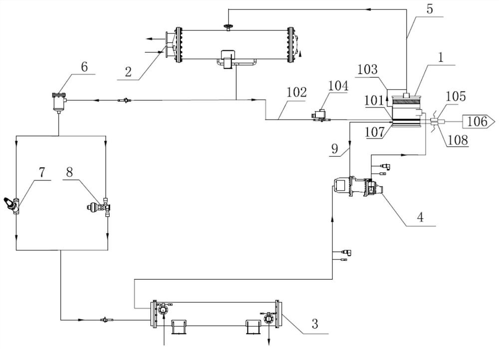
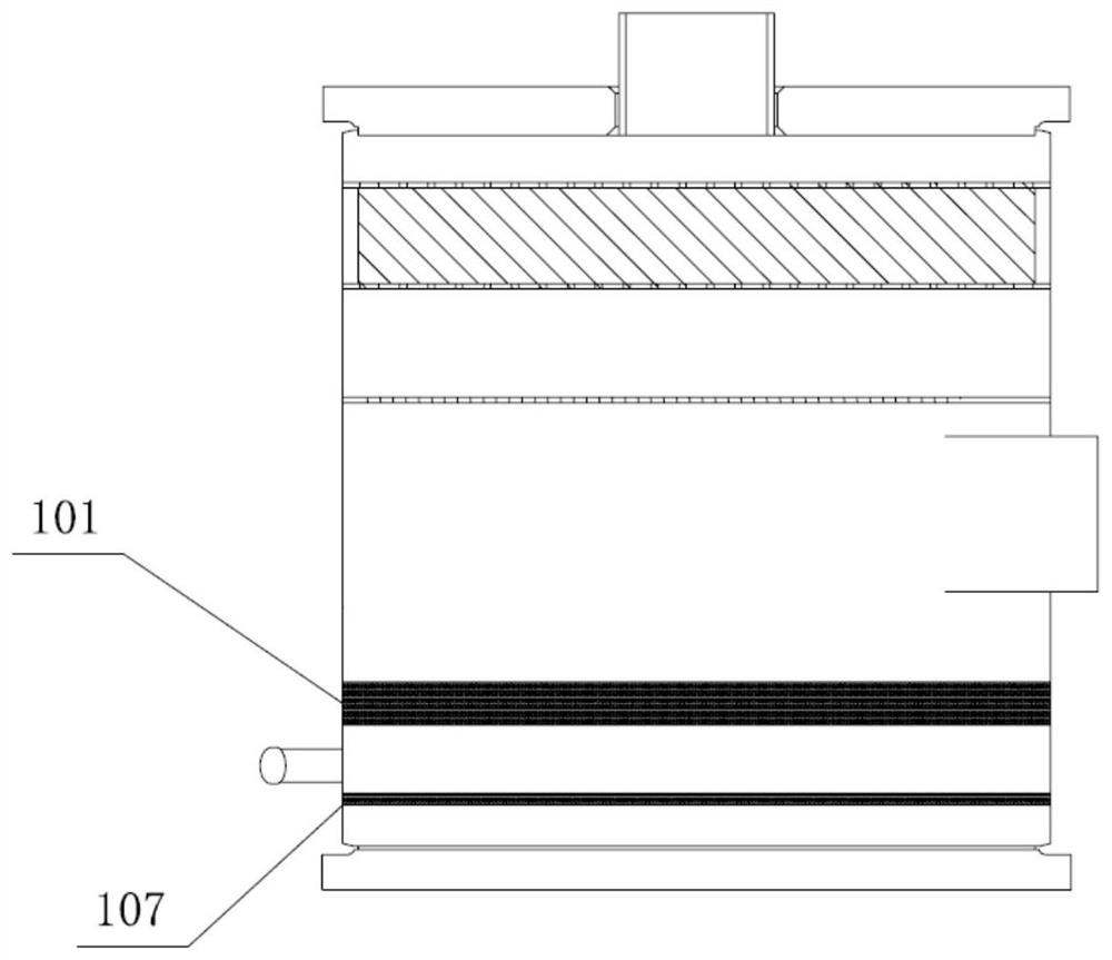
[0041] The oil temperature control mechanism of this embodiment includes a cooling pipeline 101, a cooling pipeline 102 and an air return pipeline 103, such as Figure 1 and Figure 2 As shown in. Preferably, the cooling pipeline 101 is arranged on the outer wall of the oil separator 1, the two ends of the cooling pipeline 102 are respectively connected with the refrigerant outlet end of the condenser 2 and the inlet end of the cooling pipeline 101, and the two ends of the air return pipeline 103 are respectively connected with the outlet end of the cooling pipeline 101 and the refrigerant inlet end of the condenser 2; The refrigerant in the condenser 2 enters the cooling pipeline 101 through the cooling pipeline 102 to exchange heat with the oil separator 1, and the heat exchanged refrigerant enters the refrigerant inlet end of the condenser 2 through the air return pipeline 103, as ...

Embodiment 2

[0050] The embodiment describes the oil temperature control method of the invention in detail.

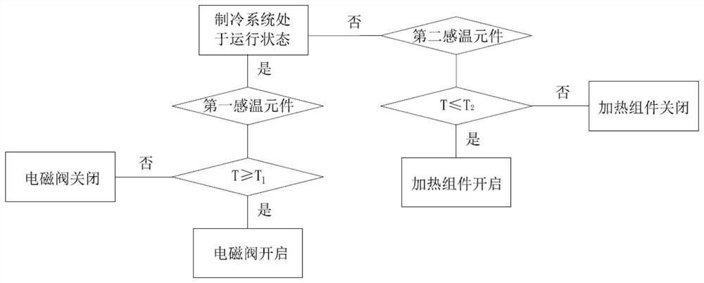
[0051] Figure 3A flow chart of a preferred embodiment of the oil temperature control method of the present embodiment is shown. as Figure 3 As shown in, the oil temperature control method using the oil temperature control mechanism of any one of embodiment 1 includes the following steps:

[0052] S1: judge the operation state of the refrigeration system.

[0053] S21: during the operation of refrigeration system, detect the lubricating oil temperature in oil separator 1. T≥T 1 Control the refrigerant flowing out of the refrigerant outlet end of condenser 2 to exchange heat with the lubricating oil in oil separator 1, and make the refrigerant after heat exchange enter the refrigerant inlet end of condenser 2; T<T 1 When, the refrigerant flowing out of the refrigerant outlet end of condenser 2 is controlled to enter evaporator 3, where t is the lubricating oil temperature in oil separat...

Embodiment 3

[0059] The embodiment describes the refrigeration system of the invention in detail.

[0060] The refrigeration system of this embodiment comprises an oil separator 1, a condenser 2, an evaporator 3, a compressor 4 and an oil temperature control mechanism, wherein the oil separator 1, the condenser 2, the evaporator 3, the compressor 4 and the oil separator 1 are successively connected and form a refrigerant circuit, such as Figure 1 As shown in. Preferably, the oil temperature control mechanism is the oil temperature control mechanism of any technical scheme in embodiment 1.

[0061] See again Figure 1 The inlet end of the refrigerant system 6 and the outlet end of the refrigerant system 9 of the embodiment are connected with the expansion valve of the refrigerant system 6 and the expansion valve of the refrigerant system 6, wherein the expansion valve of the refrigerant system 6 and the expansion valve of the embodiment are also connected with the inlet end of the refrigerant sy...


PUM


Abstract

The invention discloses an oil temperature control mechanism, a refrigerating system, an air conditioner and an oil temperature control method, relates to the field of air conditioners, and solves the problem that the temperature of lubricating oil in an oil separator is too high when a compressor operates under a low-load working condition in the prior art. The oil temperature control mechanism comprises a cooling pipeline, a cooling pipeline and an air return pipeline, the cooling pipeline is arranged on the outer wall of an oil separator, the two ends of the cooling pipeline are connected with the refrigerant outlet end of a condenser and the inlet end of the cooling pipeline respectively, and the two ends of the air return pipeline are connected with the outlet end of the cooling pipeline and the refrigerant inlet end of the condenser respectively; and a refrigerant in the condenser enters the cooling pipeline through the cooling pipeline to exchange heat with the oil separator, and the refrigerant subjected to heat exchange enters the refrigerant inlet end of the condenser through the air return pipeline. The oil temperature control mechanism not only can reduce the temperature of lubricating oil in the oil separator and improve the lubricating performance of the lubricating oil, but also has the advantages of being simple in process pipeline, low in cost and free of loss of refrigerating capacity of a unit.

Description

technical field [0001] The invention relates to the technical field of air conditioning, in particular to an oil temperature control mechanism, a refrigeration system including the oil temperature control mechanism, an air conditioner including the refrigeration system, and a method for oil temperature control using the oil temperature control mechanism. Background technology [0002] In the refrigeration system, lubricating oil plays the role of lubrication and sealing, especially in the screw compressor, lubricating oil plays the role of lubricating bearings. In the process of bearing lubrication, the lubricating performance of lubricating oil is closely related to the temperature. Too high or too low lubricating oil temperature will make the lubricity of lubricating oil worse, resulting in the wear of compressor bearings and the reduction of working life. In serious cases, it will lead to the damage of compressor. Therefore, it is necessary to keep the lubricating oil at an ap...

Claims


Application Information

Patent Timeline
IPC IPC(8): F25B43/02F25B31/00F25B39/04F25B41/20F25B49/02F04B39/02F04B39/06
CPCF25B43/02F25B31/002F25B39/04F25B41/20F25B49/02F04B39/02F04B39/064F25B2400/01F25B2500/16
Inventor 张秋梅周江峰赵阳阳王纪遇
Owner GREE ELECTRIC APPLIANCES INC OF ZHUHAI
Why Eureka
Try Eureka