One-stage planetary reduction unit and three-stage planetary reduction driver
A planetary deceleration and planetary technology, which is applied in the field of one-stage planetary deceleration unit and three-stage planetary deceleration drive, can solve the problems of low assembly efficiency, accumulation of installation errors, and low service life of gearboxes, so as to improve assembly efficiency, stability, The effect of improving the pass rate
- Summary
- Abstract
- Description
- Claims
- Application Information
AI Technical Summary
Problems solved by technology
Method used
Image

Examples
Embodiment Construction
[0033] In order to make the object, technical solution and advantages of the present invention more clear, the present invention will be further described in detail below in conjunction with the examples. It should be understood that the specific embodiments described here are only used to explain the present invention, not to limit the present invention.
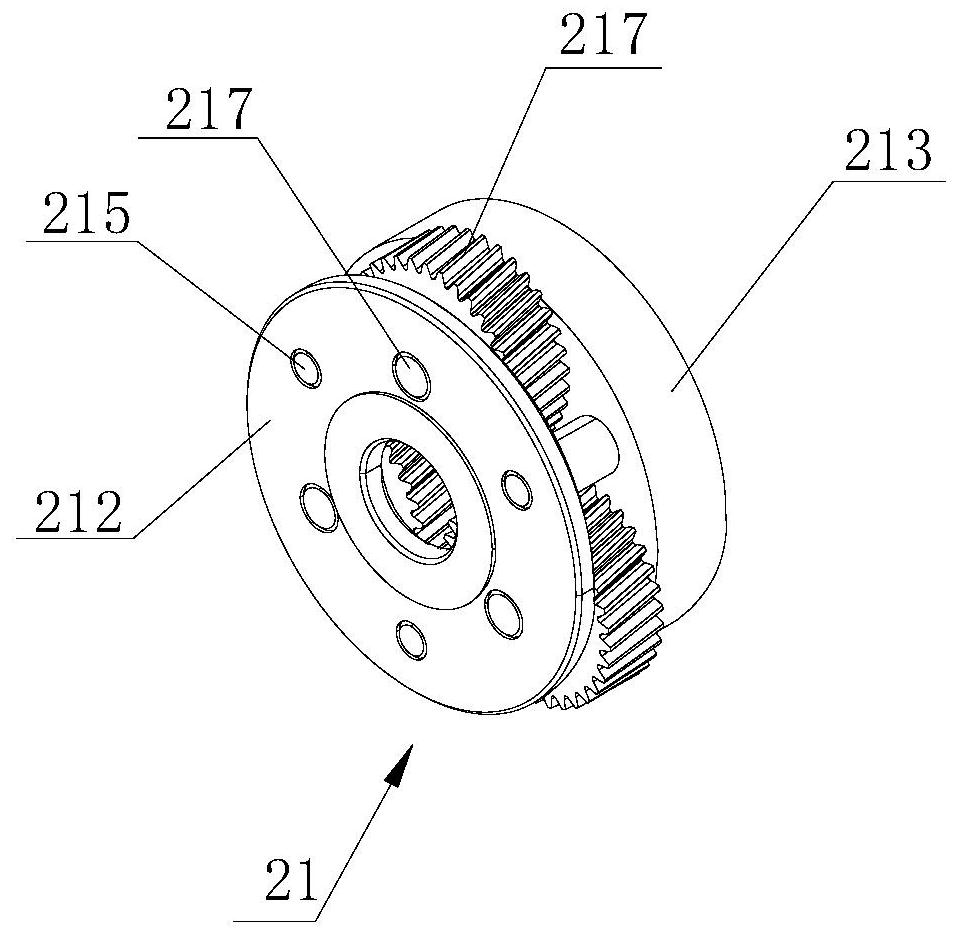
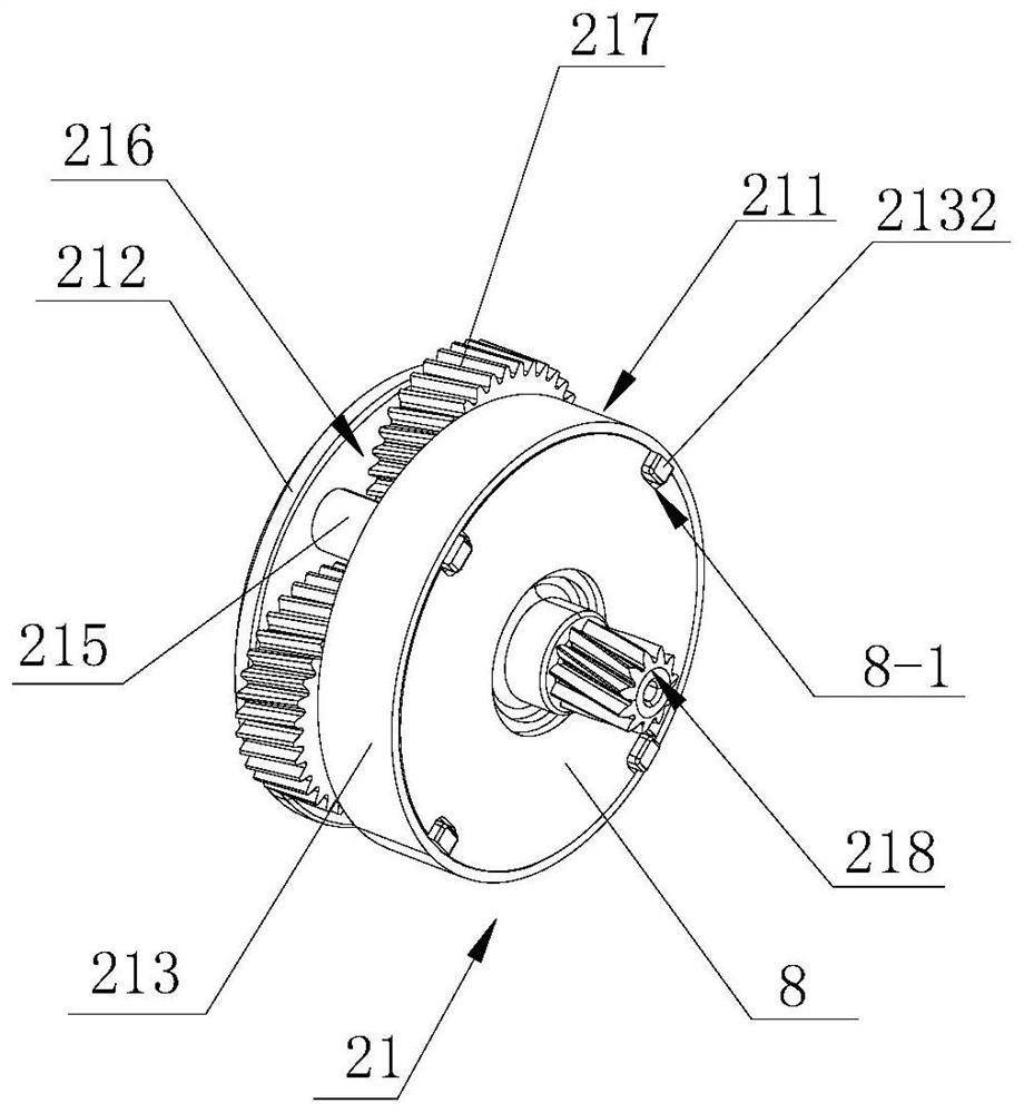
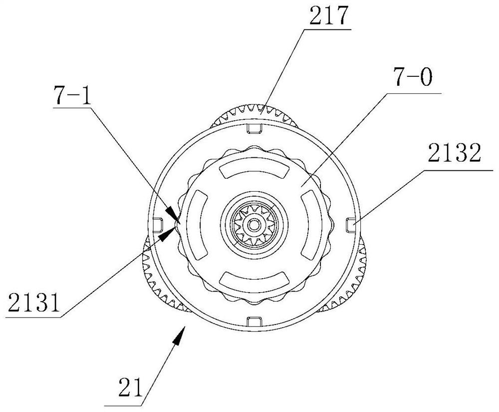
[0034] see Figure 1 to Figure 6, a primary planetary reduction unit, the primary planetary reduction unit 21 includes a primary planetary carrier assembly 211, a primary planetary gear 218 installed in the primary planetary carrier assembly; wherein the primary planetary carrier assembly includes a The primary rotary support disc 212, the primary planetary wheel 213, the primary planetary shaft 214 arranged on the primary planetary wheel, the primary planetary shaft 214 and the primary planetary wheel are integrally formed; the primary rotary support The disc is fixedly connected to the primary planetary wheel disc 213 th...
PUM
 Abstract
Description
Claims
Application Information
PatSnap Eureka turns technology decisions into work you can execute. Powered by our Innovation Knowledge Graph, it runs expert workflows across engineering, life sciences, materials and intellectual property. Get your review-ready output in minutes.


