Response type particle reinforced foam system for oil and gas development as well as preparation method and application of response type particle reinforced foam system

A foam system and particle strengthening technology, applied in chemical instruments and methods, mining fluids, earth drilling and mining, etc., can solve the problems of poor foam stability, complex synthesis process, and inconspicuous effect, and achieve easy dispersion, good response characteristics, The effect of increasing hydrophobicity

Pending Publication Date: 2022-05-10
CHINA UNIV OF PETROLEUM (EAST CHINA)
View PDF6 Cites 0 Cited by
  • Summary
  • Abstract
  • Description
  • Claims
  • Application Information

AI Technical Summary

Problems solved by technology

However, the response speed of the system is slow, and the effect is not obvious in practical applications.
Moreover, most of the existing on-off foam systems have complex synthesis processes, poor foam stability, and are not easy to use.

Method used


Image

  • Response type particle reinforced foam system for oil and gas development as well as preparation method and application of response type particle reinforced foam system
  • Response type particle reinforced foam system for oil and gas development as well as preparation method and application of response type particle reinforced foam system
  • Response type particle reinforced foam system for oil and gas development as well as preparation method and application of response type particle reinforced foam system

Examples


experiment example 1

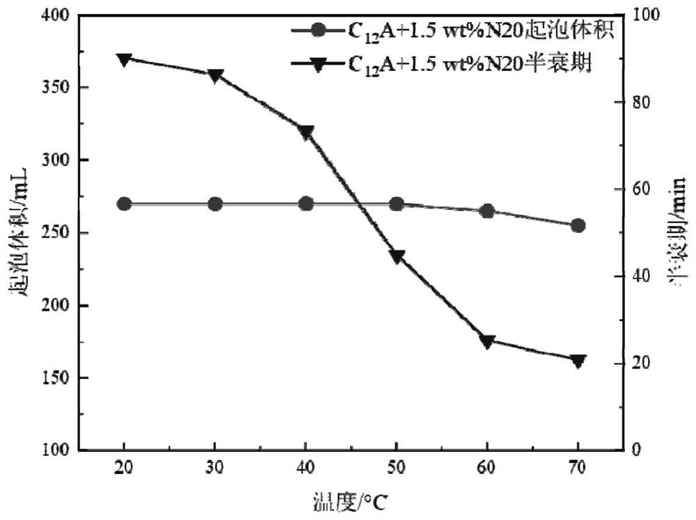
[0040] Experimental Example 1: Nanoparticles and CO at different temperatures 2 Foaming Experiment of Responsive Surfactant

[0041] A CO added with hydrophilic nanoparticles 2 Responsive foam system including raw material mass parts is composed as follows:

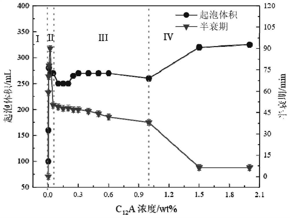
[0042] The initial concentration of nanoparticles was set at 0.5-1.5wt%, the solution volume was 100mL, and then 0.01-1.0wt% concentration of C 12 A surfactant makes up a series of solutions.

[0043] The preparation method is as follows:

[0044] (1) Use an ultrasonic processor to disperse all the dispersions at 20kHz for 8 minutes, let stand for 3 minutes, and disperse for 8 minutes to obtain a stable compound system solution.

[0045] (2) Pass the solution of the compound system through the Warning Blender method, the fixed speed is 8000r / min, and the stirring time is 3min to generate CO 2 Foam. First, pour 100mL of foaming agent solution into the foam stirrer, seal the foam stirrer with a sealing cover, and cont...

experiment example 2

[0047] Experimental Example 2: Nanoparticles and CO 2 Responsive Surfactant Foaming / Defoaming Repeatability Experiment

[0048] The operation method is as follows:

[0049] (1) First pour the compounded solution into a high-speed mixer to foam, and use a stainless steel pipeline to 2 Inject the bottom of the foam at a fixed flow rate of 2L / min, and record the defoaming process.

[0050] (2) Add CO to the defoamed solution at a flow rate of 1 L / min 2 , to be solution with CO 2 After the reaction was complete, use a high-speed mixer to foam, record the foam volume and half-life, and perform three cycles alternately. All experiments were carried out at room temperature 25°C.

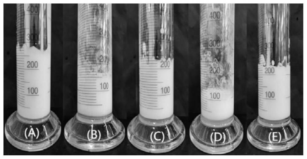
[0051] Figure 3-4 The appearance photos of the foam after repeating the foaming / defoaming of the compounded solution three times, at a room temperature of 25°C by passing CO 2 Foam can be generated, and N is passed into the bottom of the foam for 7-10 minutes 2 , the foam is basically eliminated, an...

experiment example 3

[0052] Experimental example 3: Photomicrograph experiment of taking foam

[0053] The operation method is as follows:

[0054] (1) Use a super depth-of-field 3D microscope (VHX-5000) to observe the microstructure and coalescence process of the foam at a room temperature of 25 °C. Bubble the compound system solution of 0.02wt% C12A and 1.5wt% N20 with a high-speed stirrer. Use a glass rod to transfer a small amount of foam onto a clean glass slide, spreading the foam as flat as possible on the glass slide.

[0055] (2) Adjust the focal length and the stage until the image is clear, and control the software to take a microscopic picture and use a three-dimensional scanner to analyze the liquid film of the foam.

[0056] The result is as Figure 5 As shown, after the foam adsorbed nanoparticles, the liquid film of the foam became thicker and rougher. The adsorption of nanoparticles will increase the mechanical strength of the interface, which can improve the foam stability. ...


PUM

PropertyMeasurementUnit
specific surface areaaaaaaaaaaa

Abstract

The invention provides a CO2 response type particle reinforced foam system for oil and gas development as well as a preparation method and application thereof, and belongs to the technical field of oil and gas field development engineering. The problems that in the prior art, when oil and gas are exploited, a defoaming agent needs to be added to defoam a foam system, the composition of the foam system is changed, and further refoaming is prevented; the stability is poor; the synthesis process is complex; the response speed is slow, and the switch reversibility is not strong. The system mainly comprises C12A and nanoparticles, has the characteristics of sensitivity, stability, easiness in preparation and reversible response, and can be used for technologies such as foam fracturing, sand washing and well washing in the field of oil exploitation.

Description

technical field [0001] The invention belongs to the technical field of oil and gas field development engineering, and in particular relates to a responsive particle-reinforced foam system for oil and gas development, a preparation method and an application thereof. Background technique [0002] At present, foam fluid has shown great application potential in various aspects of drilling, oil and gas well stimulation, workover, and enhanced recovery in the petroleum industry. Foam fluid generally refers to the dispersion system formed by the dispersion of insoluble or slightly soluble gas and liquid. Because the gas is surrounded by a liquid film, the foam has the advantages of low friction, low density, low filtration loss, and little damage to the formation, and the foam can block the high-permeability layer and increase the impact on the low-permeability layer. volume effect. Therefore, the foaming ability and half-life of foam are very important to the application of foam...

Claims


Application Information

Patent Timeline
Patent Type & Authority Applications(China)
IPC IPC(8): C09K8/66C09K8/68C09K8/70C09K8/58C09K8/584E21B43/26E21B43/22
CPCC09K8/68C09K8/665C09K8/703C09K8/58C09K8/584E21B43/26E21B43/16C09K2208/10
Inventor 李松岩李绍鹏魏艳写杜可欣朱建忠李兆敏
Owner CHINA UNIV OF PETROLEUM (EAST CHINA)
Why Eureka
Try Eureka