Chemical chain gasification reaction device and method thereof

A technology of gasification reaction and gasification reactor, which is applied in the field of chemical chain gasification reaction device, can solve problems such as difficult to eradicate tar escape, increase fluidization wind speed, increase fan energy consumption, etc., and achieve extensive social benefits and industrial prospects , increase productivity, and save fan energy consumption

Active Publication Date: 2022-05-10
NANJING NORMAL UNIVERSITY
View PDF4 Cites 1 Cited by
  • Summary
  • Abstract
  • Description
  • Claims
  • Application Information

AI Technical Summary

Problems solved by technology

Traditional single-stage fuel reactors, or traditional single methods, such as increasing the fluidization wind speed and using bed feeds, etc., are difficult to eradicate the problem of tar escape
[0004] The hierarchical arrangement of fuel reactors can prolong the residence time of oxygen carrier particles in the fuel reactor and improve the conversion rate of tar. It is a commonly used method for two-stage or multi-stage gasification reactors. In the prior art, hood-type air distribution panels are used for Multi-stage arrangement, this arrangement method increases the pressure drop of the fan used in the fuel reactor and increases the energy consumption of the fan

Method used


Image

  • Chemical chain gasification reaction device and method thereof
  • Chemical chain gasification reaction device and method thereof
  • Chemical chain gasification reaction device and method thereof

Examples


Embodiment 1

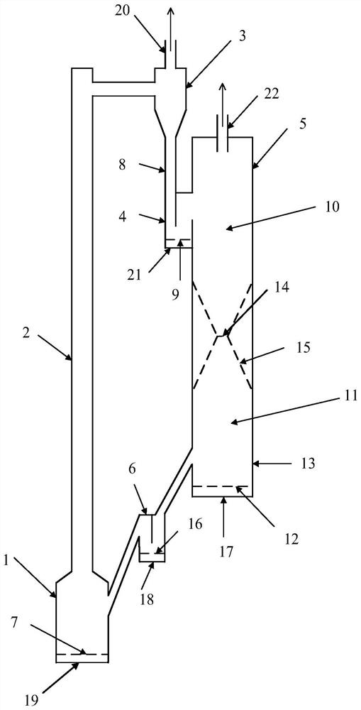
[0044] Such as figure 2 As shown, the main body of the reaction device is composed of an air reactor 1, a riser 2, a cyclone separator 3, an air reactor returner 4, a fuel reactor 5 and a fuel reactor returner 6 to form a circulating gasification reaction device. Air reactor 1 bottom is provided with air inlet 19, and air reactor air distribution plate 7 is arranged on the top of air reactor 1 bottom and air inlet 19, and the middle part of air reactor 1 side is provided with feed inlet, and air reactor The upper part of 1 is connected with the riser 2 through a pipeline, the riser 2 is connected with the cyclone separator 3 through a pipeline, the top of the cyclone 3 is provided with an oxygen-poor air outlet 20, and the upper end of the discharge pipe 8 is discharged from the bottom of the cyclone 3 The lower end of the discharge pipe 8 is connected to the top of the air reactor feeder 4, and the air reactor feeder 4 side is provided with a return port in the middle, and t...

Embodiment 2

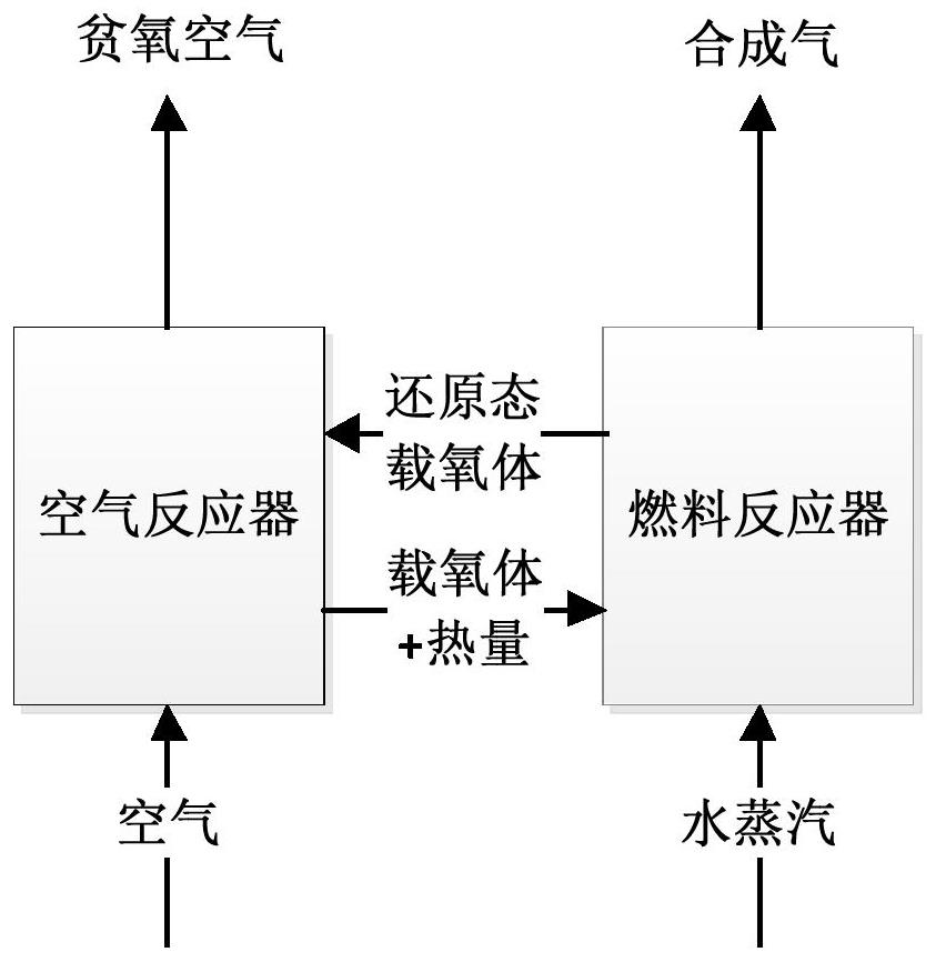
[0048] (1) Before passing into the fluidization gas, the fuel is piled up at the bottom of the gasification reactor 11, and the oxygen carrier is initially piled up at the bottom of the gasification reactor 11, the bottom of the air reactor 1, the bottom of the air reactor feeder 4 and the bottom of the air reactor 11 respectively At the bottom of the feeder 6 of the fuel reactor, the conversion of fuel to high-grade synthesis gas is realized through the circulation of oxygen carrier particles in the device.

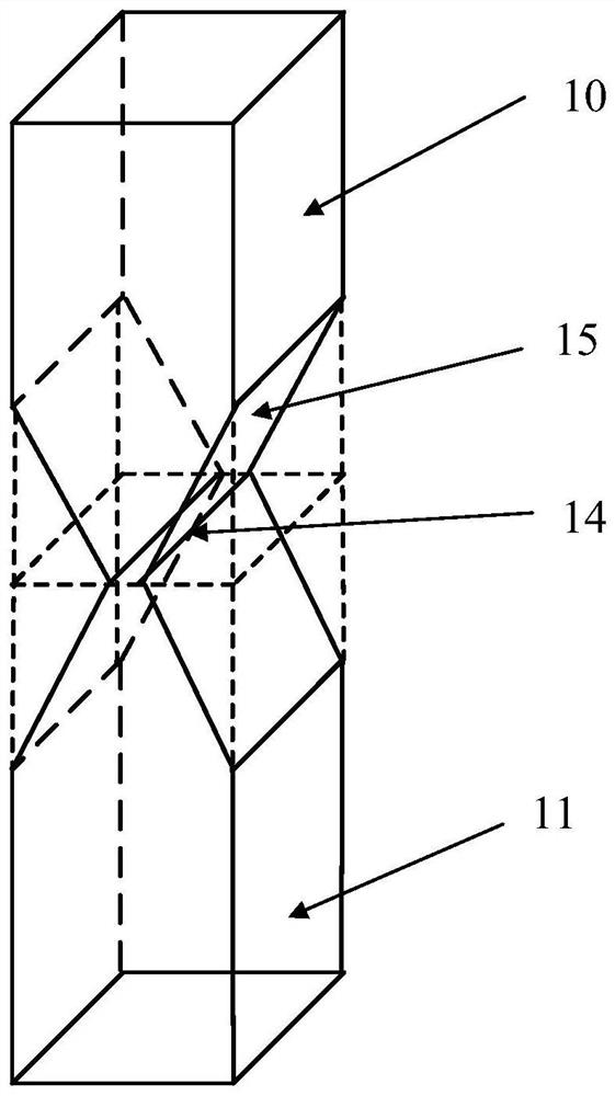
[0049] (2) The fuel enters the bottom of the gasification reactor 11, and the reaction temperature is 700°C to 1000°C. The gasification reactor 11 is a bubbling fluidized bed with a dense phase zone and a dilute phase zone, and the fuel enters the bottom of the gasification reactor 11. In the dense phase zone, the gasification medium is passed into the first gasification medium inlet 17, and the synthesis gas produced by the gasification of the fuel under the catalytic co...

Embodiment 3

[0056] The present invention builds the fuel reactor 5 of cold staged fluidization, adopts particle diameter to be 0.6mm, bulk density is 1700kg / m 3 Quartz sand particles are used as the experimental material, the superficial gas velocity is in the range of 0.1-0.7m / s in the experimental working condition, and 8 pressure measuring points (P1-P8) are arranged. Such as Figure 6 As shown, it can be clearly observed that under the appropriate material accumulation height and superficial gas velocity, bubbling fluidization appears in the gasification reactor, and the reforming reactor presents jet fluidization; at the same time, the reforming reaction Particles in the reactor gradually fall into the gasification reactor, forming the communication of the particles inside the fuel reactor.

[0057] At the same time, compared with the conventional air distribution plate connection method, the gasification reactor and the reforming reactor adopted in the present invention are connect...


PUM

PropertyMeasurementUnit
particle diameteraaaaaaaaaa
densityaaaaaaaaaa

Abstract

The invention discloses a chemical chain gasification reaction device and method. The device is a solid particle circulation loop composed of an air reactor, a lifting pipe, a cyclone separator, a return feeder and a fuel reactor. The fuel reactor comprises a gasification reactor at the lower part and a reforming reactor at the upper part which are connected through a contracted rectangular nozzle; fuel is gasified in the gasification reactor, and eluted coke and tar enter the reforming reactor through the rectangular nozzle and are catalytically converted into synthesis gas; and the reduced oxygen carrier enters the air reactor through the return feeder for oxidation and regeneration, enters the cyclone separator through the lifting pipe for separation, enters the reforming reactor through the return feeder, and falls into the gasification reactor through the rectangular slit, so that the cyclic utilization of oxygen carrier particles in the circulating fluidized bed is completed. The device reduces the pressure drop of the reactor and effectively saves the energy consumption of a fan through staged fluidization of the fuel reactor and fluidization reconstruction.

Description

technical field [0001] The invention relates to a chemical chain gasification reaction device and a method thereof. Background technique [0002] Chemical-Looping Gasification (GLG) technology is a novel gasification method, which has a similar principle to Chemical-Looping Combustion (CLC), both of which use metal or non-metal oxides to provide fuel Oxygen required for the reaction, by controlling the lattice oxygen / fuel ratio to obtain the target product. Such as figure 1 As shown, from the perspective of oxygen utilization, chemical looping gasification no longer uses pure oxygen directly, but relies on the lattice oxygen contained in the circulating metal oxide (oxygen carrier) particles, which will chemically react with oxygen in the air to The oxygen in the air reactor is transported to the fuel reactor to realize the process of carrying oxygen and transferring oxygen; at the same time, the circulating solid particles in the reactor are oxygen carriers with significa...

Claims


Application Information

Patent Timeline
Patent Type & Authority Applications(China)
IPC IPC(8): C10J3/60C10J3/72C10J3/82
CPCC10J3/60C10J3/721C10J3/82
Inventor 宋涛郭月殷上轶卢平
Owner NANJING NORMAL UNIVERSITY
Why Eureka
Try Eureka