Quantum key distribution coding device

A technology of quantum key distribution and encoding devices, which is applied in the field of quantum key distribution encoding devices, can solve problems such as inability to implement protocols or encoding methods, incompatibility with other protocols or encoding methods, increase system complexity and cost, and achieve Improve stability and practicability, increase security code rate, and stabilize encoding effect

Active Publication Date: 2022-05-10
北京中科国光量子科技有限公司
View PDF5 Cites 1 Cited by
  • Summary
  • Abstract
  • Description
  • Claims
  • Application Information

AI Technical Summary

Problems solved by technology

[0003] At present, for a specific protocol or a specific protocol encoding method, it is necessary to design a corresponding optical path to realize the protocol or encoding method, and most of them are not compatible with other protocols or encoding methods
Therefore, the encoding device lacks versatility, and cannot realize the switching of protocols or encoding methods according to the needs of practical applications, so as to meet the optimization of system performance.
According to the existing technology, in order to realize the switching of protocols or coding methods, it is necessary to cascade special coding devices for multiple protocols or coding methods, which greatly increases the complexity and cost of the system

Method used


Image

  • Quantum key distribution coding device
  • Quantum key distribution coding device
  • Quantum key distribution coding device

Examples


Embodiment 1

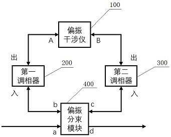
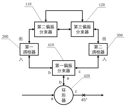
[0055] The structure of the encoding device is: the polarization beam splitting module 400 includes a circulator 420 and a first polarization beam splitter 410, the port a of the circulator 420 is used as the port a of the polarization beam splitting module 400; the circulator Port b of 420 is connected to port a of the first polarization beam splitter 410; port b and port c of the first polarization beam splitter 410 are respectively used as port b and port c of the polarization beam splitting module 400; the circulator The output polarization-maintaining fiber of port c of 420 is fused at 45° to serve as port d of the polarization splitting module 400 . The polarization interferometer 100 includes a second polarization beam splitter 110 and a third polarization beam splitter 120, and each of the second polarization beam splitter 110 and the third polarization beam splitter 120 includes an input port and two output ports The input ports of the second polarization beam splitte...

Embodiment 2

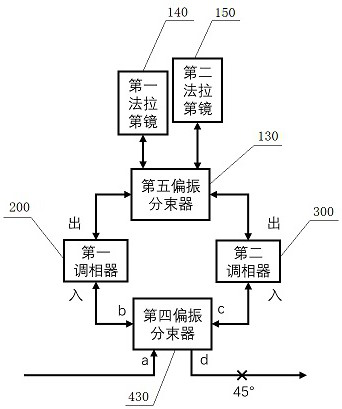
[0060] The structure of the encoding device is as follows: the polarization beam splitting module 400 is a fourth polarization beam splitter 430, and the ports a-c of the fourth polarization beam splitter 430 are respectively used as ports a-c of the polarization beam splitting module 400; The output polarization-maintaining fiber of port d of the four-polarization beam splitter 430 is spliced ​​at 45° to serve as port d of the polarization splitting module 400 . The polarization interferometer 100 includes a fifth polarization beam splitter 130, a first Faraday mirror 140, and a second Faraday mirror 150, and the fifth polarization beam splitter 130 includes two input ports and two output ports, so The two input ports of the fifth polarization beam splitter 130 are respectively used as port A and port B of the polarization interferometer 100, and the two output ports of the fifth polarization beam splitter 130 are respectively connected to the first optical fiber through two o...

Embodiment 3

[0065] The structure of the encoding device is: the polarization beam splitting module 400 includes a first beam splitter 460, a first polarizer 440, a second polarizer 450 and a third polarizer 470, and the first beam splitter 460 port a is used as the port a of the polarization beam splitting module 400; the ports b-d of the first beam splitter 460 are respectively connected to the input ports of the second polarizer 450, the third polarizer 470 and the first polarizer 440, wherein The polarization-maintaining fiber between the port d of the first beam splitter 460 and the first polarizer 440 is fused at 45°; the output port of the second polarizer 450, the third polarizer 470 and the first polarizer 440 Ports b-d of the polarization beam splitting module 400 respectively; the polarization directions of the first polarizer 440 and the second polarizer 450 are aligned with the horizontal polarization direction, and the polarization direction of the third polarizer 470 is align...


PUM


Abstract

A quantum key distribution encoding device comprises a polarization interferometer, a first phase modulator, a second phase modulator and a polarization beam splitting module, and a port a of the polarization beam splitting module is an input port of the encoding device; a port b of the polarization beam splitting module and a port A of the polarization interferometer are respectively connected with an input port of the first phase modulator and an output port of the first phase modulator, and a port c of the polarization beam splitting module and a port B of the polarization interferometer are respectively connected with an input port of the second phase modulator and an output port of the second phase modulator to form a Sagnac ring. Compared with the prior art, six polarization states can be stably prepared, multiple lasers are not needed, safety loopholes caused by inconsistent wavelengths of the multiple lasers are eliminated, the prepared polarization states are very stable, any compensation is not needed, a receiving end only needs two single-photon detectors, and the complexity and cost of the system are reduced. In addition, the polarization coding device can be used for realizing a BB84 protocol, a 6-state protocol and a reference system independent protocol.

Description

technical field [0001] The invention relates to the technical field of quantum phase encoding, in particular to a quantum key distribution encoding device. Background technique [0002] Quantum key distribution has the security of information theory, and its security is guaranteed by the basic principles of quantum mechanics. It can resist the threat from quantum computers and plays an important role in secure communication. Among the quantum key distribution (QKD) protocols, the BB84 protocol was first proposed. With the development of theory and experiments, various protocols have been proposed one after another, such as the six-state protocol, the reference frame independent protocol, etc., in various applications Each scenario has its own advantages. The encoding states that can realize the above-mentioned various protocols at the same time are various superposition states of the modes |0> and |1>, generally including three groups of basis vectors, X basis, Y basi...

Claims


Application Information

Patent Timeline
Patent Type & Authority Applications(China)
IPC IPC(8): H04L9/08H04B10/70H04B10/532
CPCH04L9/0858H04B10/70H04B10/532
Inventor 赵义博王东陈东升
Owner 北京中科国光量子科技有限公司
Why Eureka
Try Eureka