Laser welding clamp with double-sided inert gas protection

A laser welding fixture, inert gas technology, applied in laser welding equipment, welding equipment, welding equipment and other directions, can solve the problem of poor shielding gas protection, only contact with the back of the weld, and unable to achieve shielding gas protection, etc. Achieve the effect of improving the shielding effect of the shielding gas, realizing high-quality welding, and enhancing the protective effect.

Pending Publication Date: 2022-05-13
NANJING UNIV OF SCI & TECH
View PDF11 Cites 0 Cited by
  • Summary
  • Abstract
  • Description
  • Claims
  • Application Information

AI Technical Summary

Problems solved by technology

Ordinary laser welding fixtures only have the functions of pressing and positioning. The gas protection device is on the welding head. Whether it is coaxial or side-axis gas supply, the quality of the weld seam will still be due to poor shielding gas protection, and welding problems will occur.
[0004] Patent CN213916722U discloses a gas shielding device for laser welding. By setting compression fixtures respectively on the top surface of the cover plate where the two sides of the through hole are located, and by setting the first chamber in the cavity body, the gas inlet joint can be used to seal the gas. Shielding gas is introduced into the chamber, and the gas flows out through the strip holes at the bottom of the carrier plate along the vent holes on the flow guide, but the workpiece is located above the chamber, so the shielding gas can only contact the back of the weld, although the back has a protective effect, but Unable to achieve positive shielding gas protection

Method used


Image

  • Laser welding clamp with double-sided inert gas protection
  • Laser welding clamp with double-sided inert gas protection

Examples


Embodiment Construction

[0027] The present invention will be described in further detail below in conjunction with the accompanying drawings.

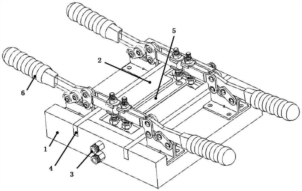
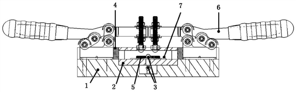
[0028] Such as Figure 1-2 As shown, a special fixture for laser welding with inert gas protection is provided with a ventilating base 1, a stage 2 arranged in the groove above the ventilating base 1, arranged on both sides of the stage 2 and passing through the ventilating base 1 The baffle plates 4 of the small grooves on both sides have a protective air groove at the center of the ventilation base 1, and two air holes are arranged in the protective air groove and above the protective air groove and are connected with the air nozzle 3. When in use, at first the quick clamp 6 is fixed on the ventilation base 1 by screws, the loading platform 2 is placed inside the ventilation base 1, the two pressing blocks 5 are placed in the loading platform 2, and the test plate 7 to be welded is butted on the The stage 2 is placed on the groove and pressed under the two...


PUM


Abstract

The invention relates to a laser welding clamp with double-sided inert gas protection. Comprising a ventilation base, an objective table, a ventilation nozzle, a baffle, a pressing block and a clamp. An objective table mounting groove is formed in the middle of the ventilation base, and a protective gas groove communicating with the objective table mounting groove is formed in the lower side of the middle of the objective table mounting groove; the objective table comprises an upper plate, a lower plate and a stand column connected with the upper plate and the lower plate, the upper plate is provided with an I-shaped groove, and the upper plate and the lower plate of the objective table, a baffle on the long side and a ventilation base body on the short side form a relatively sealed cavity; each side surface of the ventilation base is provided with two ventilation nozzles up and down; a test piece to be welded is placed on the lower plate, the clamp tightly presses the test piece through the pressing block, and the welding gun conducts welding through the long groove of the I-shaped groove. The objective table and the ventilation base are matched to form a relatively-closed protective gas chamber, the front face and the back face of a welding seam are protected by protective gas, the problems of air hole generation, oxidation, element burning loss, structure overburning and the like of the welding seam can be prevented, and the welding quality is improved.

Description

technical field [0001] The invention belongs to the field of welding fixtures, in particular to a laser welding fixture with double-sided inert gas protection. Background technique [0002] Laser welding technology has the characteristics of short action time, high efficiency, fast speed, small deformation, high weld quality, high welding precision, and easy automation. It is gradually replacing traditional welding in the fields of automobiles, trains, ships, aerospace, and machinery manufacturing. The arc welding process is widely used. [0003] In the process of laser welding, in order to avoid the problem of oxidation pollution under high temperature conditions, it is generally necessary to protect the weld seam, and the usual method is to use inert gas protection. Ordinary laser welding fixtures only have the functions of pressing and positioning, and the gas protection device is on the welding head. No matter whether it is coaxial gas supply or side-axis gas supply, th...

Claims


Application Information

Patent Timeline
Patent Type & Authority Applications(China)
IPC IPC(8): B23K37/04B23K26/70B23K26/21
CPCB23K37/0443B23K26/702B23K26/21
Inventor 李晓鹏韩瑞蒋晗彭勇王克鸿王大森
Owner NANJING UNIV OF SCI & TECH
Why Eureka
Try Eureka