Satellite-borne flat plate type antenna gravity unloading device and method

A gravity unloading and flat-plate technology, which is applied in the field of aerospace satellites, can solve the problems of undocumented design methods of gravity unloading tooling, and achieve the effects of fast positioning and evacuation, vertical suspension, and convenient maintenance

Active Publication Date: 2022-05-13
SHANGHAI SATELLITE ENG INST
View PDF8 Cites 1 Cited by
  • Summary
  • Abstract
  • Description
  • Claims
  • Application Information

AI Technical Summary

Problems solved by technology

[0004] At present, in the open literature and information, there is no record about the design method of the gravity unloading tool for the ground deployment test of the flat antenna

Method used


Image

  • Satellite-borne flat plate type antenna gravity unloading device and method
  • Satellite-borne flat plate type antenna gravity unloading device and method
  • Satellite-borne flat plate type antenna gravity unloading device and method

Examples


Embodiment 1

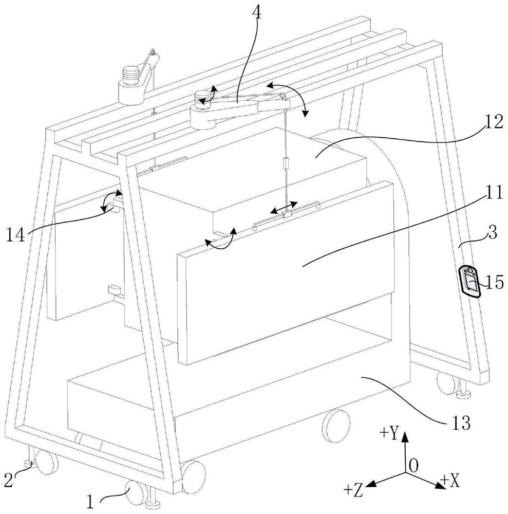
[0038] The invention provides a gravity unloading device for a satellite-borne flat plate antenna, which includes a gantry frame 3 and a steel wire winding device, the top of the gantry frame 3 is rotatably connected to a steel wire winding device for adjusting the suspension tension, and the steel wire winding device is lifted to be unfolded for testing The flat-panel antenna 11 makes it maintain gravity balance.

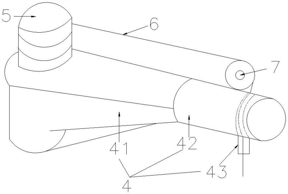
[0039] The steel wire winding device includes a cantilever frame 4, a steel wire rope rotating drum 5, a steel wire rope 6 and a pulley 7. Two cantilever frames 4 are symmetrically rotated and connected to both sides of the top of the gantry frame 3, so as to facilitate simultaneous lifting of two flat-panel antennas 11. Reduce time and improve efficiency. Preferably, a cantilever frame 4 is installed on both sides near the top of the gantry frame 3, and the cantilever frame 4 is made of stainless steel 0Cr18Ni9 with a length of 800mm and a height of 150mm. One en...

Embodiment 2

[0048] This embodiment 2 is formed on the basis of embodiment 1. Through the structural optimization of the steel wire rope rotating cylinder and the overall automatic control of the gantry frame, the specific numericalization of the wire rope tension is basically realized, and the gravity balance after the flat-panel antenna is hoisted is realized. Precision, strengthen the overall accuracy of the structure, and improve work efficiency. specific:

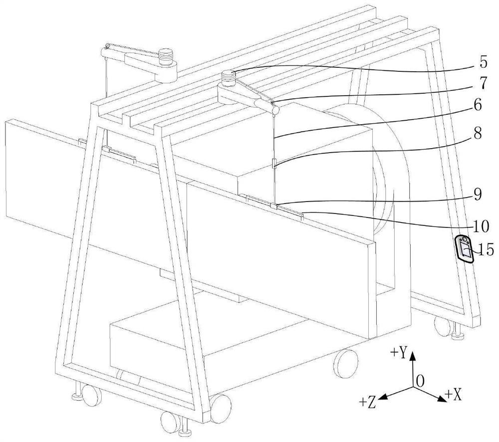
[0049] The gantry frame 3 is connected to the control 15, and the signal of the controller 15 is connected to the wire rope rotating drum 5 and the tension gauge 8. Preferably, the tension gauge 8 is a high-precision digital display readable tension gauge, and the tension gauge range is 1200N. The top of tension gauge 8 is connected with steel wire rope 6, and the lower end of tension gauge 8 is connected with the top of slide block 9 through steel wire rope 6. Preferably, steel wire rope 6 is selected Φ8mm steel wire rope, and its...

Embodiment 3

[0052] This embodiment 3 is formed on the basis of embodiment 1 or embodiment 2. Through the further sliding limit of the universal wheel to the gantry frame, the arbitrary movement of the gantry frame is basically realized, and the practicality of the brake disc can effectively complete the movement. The rear gantry frame is braked to keep its position unchanged. specific:

[0053] A plurality of universal wheels 1 are symmetrically installed on the bottom of the gantry frame 3 . Preferably, the universal wheel 1 adopts a polyurethane universal wheel with a diameter of Φ200mm, which enables the gantry frame 3 to move 360° without dead ends.

[0054] A plurality of brake discs 2 are symmetrically installed on the bottom of the gantry frame 3 . Preferably, the brake discs 2 are installed on the side of the universal wheel 1, and the number is equal. Preferably, a rubber pad with a diameter of Φ100 mm and a thickness of 20 mm is attached to the bottom of the brake disc 2 to p...


PUM


Abstract

The invention relates to a satellite-borne flat plate type antenna gravity unloading device and method in the field of spaceflight satellites, the satellite-borne flat plate type antenna gravity unloading device comprises a gantry frame and a steel wire winding device, the top of the gantry frame is rotationally connected with the steel wire winding device for adjusting suspension tension, and the steel wire winding device lifts a flat plate type antenna to be subjected to an unfolding test to enable the flat plate type antenna to keep gravity balance. According to the invention, the influence of earth gravity on the flat plate type antenna is eliminated through a cantilever frame gravity unloading method under the condition that the structural forms of the flat plate type antenna and the unfolding mechanism thereof are not changed and the system characteristics of an on-satellite unfolding controller are not changed, and the working environment of the flat plate type antenna under the condition of space weightlessness can be simulated.

Description

technical field [0001] The invention relates to the field of aerospace satellites, in particular to a gravity unloading device and method for a flat panel antenna onboard. In particular, a gravity unloading device and method for a mobile gantry-type satellite-borne flat-panel antenna. Background technique [0002] In order to ensure that the space-borne flat-panel antenna can be normally deployed and locked after the satellite is launched into orbit, it is necessary to simulate the deployment function of the flat-panel antenna in the on-orbit weightlessness environment on the ground, and then verify the working performance of the flat-panel antenna. Space-borne flat-panel antennas generally have the characteristics of large size, heavy weight, and high precision of the unfolding mechanism. In order to adapt to the envelope limit of the launch vehicle fairing, the space-borne flat-panel antenna is generally folded and compressed on the side of the satellite star through the u...

Claims


Application Information

Patent Timeline
Patent Type & Authority Applications(China)
IPC IPC(8): B64G7/00B66C23/02B66C23/36B66C23/62B66C23/84B66C9/08
CPCB64G7/00B66C23/022B66C23/36B66C23/62B66C23/84B66C9/08
Inventor 陈汀陈国忠
Owner SHANGHAI SATELLITE ENG INST
Why Eureka
Try Eureka