Mechanism for tensioning workpiece through electric screw tensioning shaft, regulation and control method and application

An electric screw and mechanism control technology, which is applied in the mechanism field of electric screw tensioning shaft tensioning workpieces, can solve problems such as low efficiency, high labor intensity, and limited air pump pressure, so as to reduce operator errors, save operation time, The effect of reducing operation time

Pending Publication Date: 2022-05-13
WUHAN GUANYOU TECH CO LTD
View PDF1 Cites 0 Cited by
  • Summary
  • Abstract
  • Description
  • Claims
  • Application Information

AI Technical Summary

Problems solved by technology

[0011] The expansion shaft has the following disadvantages in the process of use: (1) The inflated air bag will remove the air source after the expansion block is tightened, and cannot continue to ventilate and tighten, and the pressure of the air pump is limited, and the tension force is not large
(2) The reliability is not high: the mechanism requires high sealing performance. Once the air leaks, the workpiece will lose its tension during work, and the product will be scrapped or even an accident will occur.
[0012] The manual mechanical tensioner has the following disadvantages in the process of use: (1) Inconvenient to use: when replacing the reel core, it is necessary to manually loosen the thread, resulting in high labor intensity
(2) The tensioning of the manual mechanical tensioning shaft does not meet the requirements for equipment automation upgrades
[0016] The significance of solving the above problems and defects is: in view of the defects in the prior art, the purpose of this application is to provide a mechanism and method for tightening workpieces with electric screw tensioning shafts on high-speed rotating mechanisms, so as to solve the problems in the related art. The problems of poor tensioning effect, high labor intensity and low efficiency, while the tensioning force is controllable

Method used


Image

  • Mechanism for tensioning workpiece through electric screw tensioning shaft, regulation and control method and application
  • Mechanism for tensioning workpiece through electric screw tensioning shaft, regulation and control method and application
  • Mechanism for tensioning workpiece through electric screw tensioning shaft, regulation and control method and application

Examples


Embodiment Construction

[0048] In order to make the object, technical solution and advantages of the present invention more clear, the present invention will be further described in detail below in conjunction with the examples. It should be understood that the specific embodiments described here are only used to explain the present invention, not to limit the present invention.

[0049] Examples are explained. In order to make those skilled in the art fully understand how to implement the present invention, this part is an explanatory embodiment for explaining the technical solution of the claims.

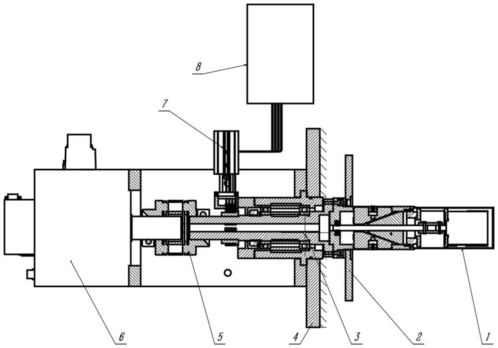
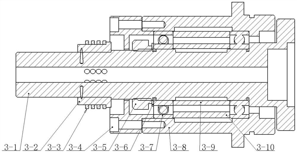
[0050] Such as Figure 1-Figure 4 As shown, the high-speed motor 6 is installed on the base of the mechanism 4 used for tightening the workpiece by the electric screw tensioning shaft on the high-speed rotating mechanism provided by the embodiment of the present invention; the front end of the high-speed motor 6 is connected to the rotary shaft 3- 1. The rotary shaft 3-1 is mainly equipped with 3-2 bak...


PUM


Abstract

The invention belongs to the technical field of tensioning of workpieces through electric screw tensioning shafts in high-speed rotating machines, and discloses a mechanism for tensioning the workpieces through the electric screw tensioning shafts, a regulation and control method and application. And the cone nut pushes the tensioning claws in the inclined plane guide groove to stretch out and retract along the peripheral surface to realize tensioning or loosening in the front-back movement process. According to the mechanism for tensioning the workpiece through the electric screw tensioning shaft on the high-speed rotating mechanism, due to the fact that a screw nut kinematic pair has the self-locking capacity and is large in pushing force, rapid tensioning of the workpiece is guaranteed, and tensioning is reliable. The mechanism for tensioning the workpiece through the electric screw tensioning shaft adopts a motor to drive a screw nut kinematic pair to adjust the tensioning force, and the tensioning force can be known and controllable. The defects existing in the using process of the expansion shaft, the using process of a manual mechanical expansion shaft and the using process of an electric drive expansion shaft are overcome.

Description

technical field [0001] The invention belongs to the technical field of tensioning workpieces with electric screw tensioning shafts in high-speed rotating machines, and in particular relates to a mechanism, control method and application for tightening workpieces with electric screw tensioning shafts. Background technique [0002] At present, in the technical fields of printing equipment and rewinding equipment in the tobacco industry, especially in laser punching equipment for tipping paper, it is necessary to fix the paper core on the tensioning shaft of the rotating mechanism, and fix and position the tipping shaft through the tensioning shaft. The core of the paper, and then the winding and unwinding reel rotates to complete various work requirements. [0003] In the prior art, there are three ways to tighten the tensioner shaft: [0004] 1. Pneumatic tensioner shaft (also known as pneumatic tensioner shaft): [0005] The pneumatic expansion shaft is an inflatable expan...

Claims


Application Information

Patent Timeline
Patent Type & Authority Applications(China)
IPC IPC(8): B65H16/10B65H18/10B65H75/24
CPCB65H16/103B65H18/10B65H75/242
Inventor 张向明李露
Owner WUHAN GUANYOU TECH CO LTD
Why Eureka
Try Eureka