Dynamic separation and recovery device for water-based paint cleaning solvent and driving control method

A technology of separation and recovery, water-based paint, applied in chemical instruments and methods, reflux water treatment, water/sewage treatment, etc., can solve problems such as wasting time, achieve high economic value, high recovery rate, and improve time-consuming efficiency.

Pending Publication Date: 2022-05-13
北京海得科过滤技术有限公司
View PDF4 Cites 1 Cited by
  • Summary
  • Abstract
  • Description
  • Claims
  • Application Information

AI Technical Summary

Problems solved by technology

When standing and settling before filtration, if you wait for the sediment to settle completely

Method used


Image

  • Dynamic separation and recovery device for water-based paint cleaning solvent and driving control method
  • Dynamic separation and recovery device for water-based paint cleaning solvent and driving control method
  • Dynamic separation and recovery device for water-based paint cleaning solvent and driving control method

Examples


Embodiment 1

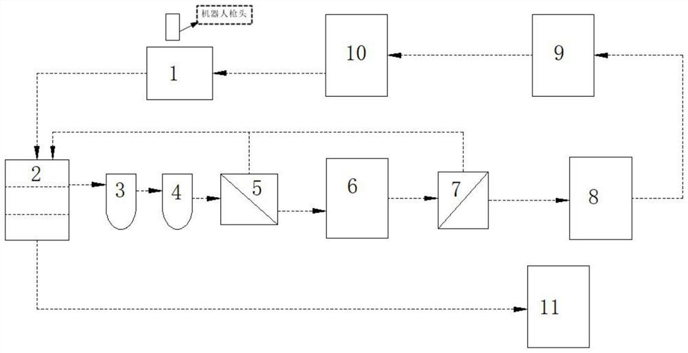
[0029] see figure 1 , in this invention:

[0030] In the automatic spraying process of car paint and other workshops, a large amount of spray paint is attached to the robot gun head, and the cleaning liquid cleans the robot gun head, and the cleaning liquid enters the cleaning toilet 1, and the liquid collected in the cleaning toilet 1 is transferred to the original liquid tank 2 , the solvent cleaning solution enters the stock solution tank 2 for static settlement. After the clear liquid left standing in the raw liquid tank 2 is filtered by the primary filter bag 3, the 5um filter element 4 and the UF membrane 5 [the filtration accuracy of the UF membrane 5 can reach 0.01um], the preliminary clear liquid is transferred to the primary clear liquid tank 6 , and then filtered through the RO membrane 7 [filter precision up to 0.001um], the clear liquid filtered through the RO membrane 7 enters the recovery solution tank 8, and the concentrated liquid filtered out by the UF membr...

Embodiment 2

[0034] see figure 1 , figure 2 , image 3 , in this invention:

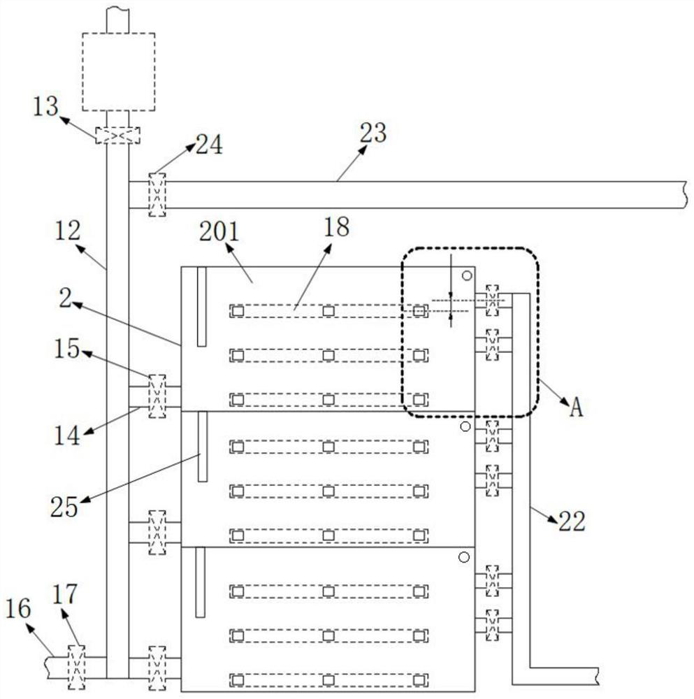
[0035] The stock solution tank 2 is divided into a plurality of separation chambers 201, and each separation chamber 201 is equipped with a multi-layer photoelectric detection belt 18, and a plurality of photoelectric probes 19 are arranged in the photoelectric detection belt 18 of each layer. 19 are neatly arranged at the same height, and the liquid turbidity at each position at the same height in the separation chamber 201 is detected. The turbidity of the liquid at the position of this layer also meets the requirements of the preliminary standing clear liquid.

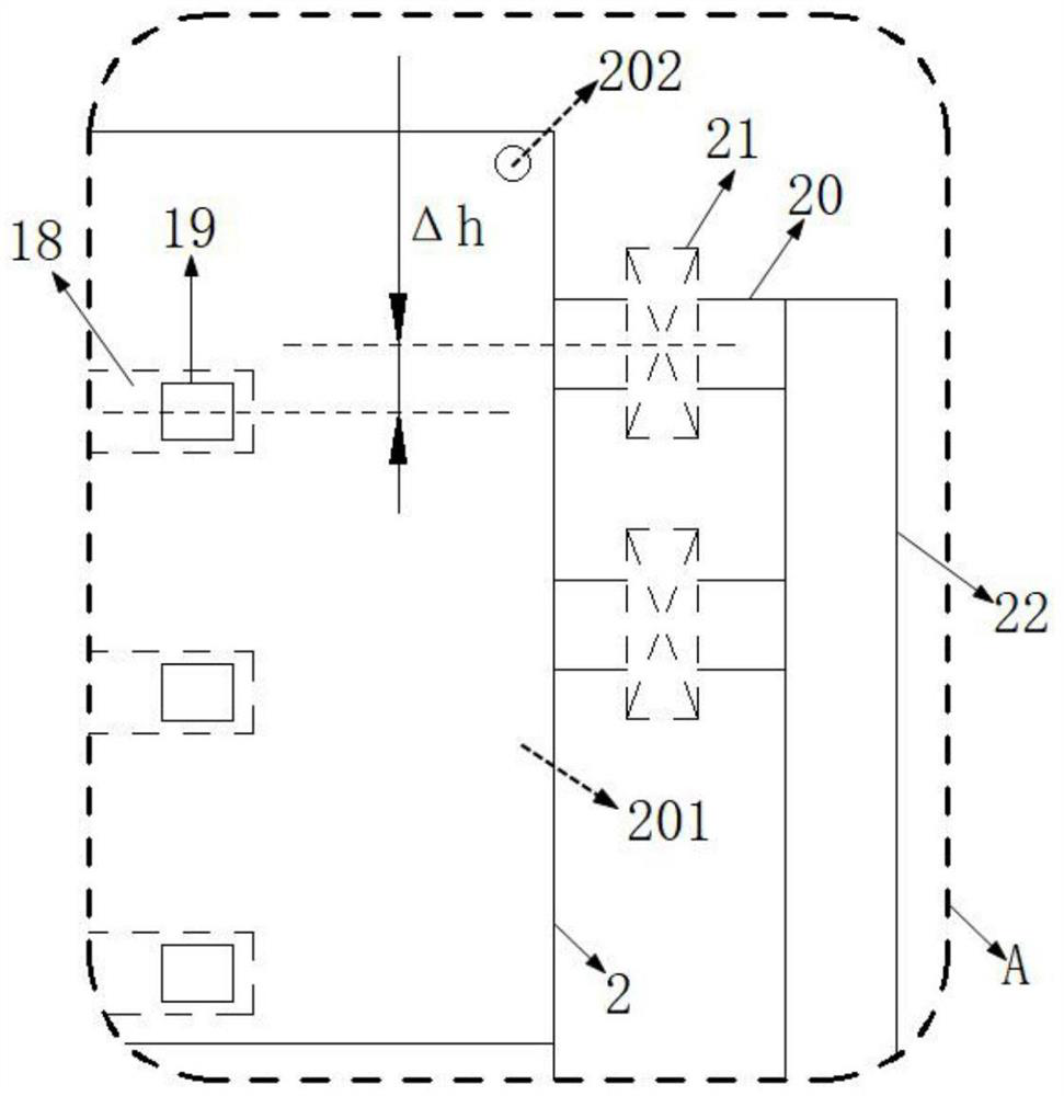
[0036]One side of the separation chamber 201 is connected with a connecting branch pipe 14 matching the position of the bottom photoelectric detection belt 18, and the other side is connected with a plurality of suction branch pipes 20 matching the position of the non-bottom photoelectric detection belt 18. Note that there is generally one connect...

Embodiment 3

[0039] see figure 2 , image 3 , in this invention:

[0040] The separation chamber 201 of the raw liquid tank 2 is equipped with a liquid level gauge 25 for sensing and detecting the liquid level height in the separation chamber 201. The control system presets the maximum saturation liquid level of the separation chamber 201, and the liquid level gauge 25 detects When the maximum saturated liquid level is reached, the control system isolates the separation chamber 201 from the outside world, and the separation chamber 201 is left to settle.

[0041] The liquid level gauge 25 adopts a non-full-section design, but it needs to measure the liquid level above the bottom photoelectric detection zone 18 to assist in judging whether to close the suction branch pipe 20 at the corresponding height. For example, after the water level has been lower than the suction branch pipe 20 of the topmost position [but not lower than the photoelectric detection zone 18 of the highest level, but...


PUM


Abstract

The invention discloses a dynamic separation and recovery device for a water-based paint cleaning solvent and a driving control method, and relates to the technical field of water-based paint cleaning solvent recovery. A cleaning solvent is collected through a cleaning closestool and enters a stock solution tank for standing and settling, supernatant liquid is filtered through a primary 50-micron filter bag, a 5-micron filter element and a UF membrane, then liquid is guided into a first-stage clear liquid tank, liquid in the first-stage clear liquid tank is filtered through an RO membrane, clear liquid enters a recovery solution tank, concentrated liquid filtered out through the UF membrane and the RO membrane flows back to the stock solution tank, and the concentrated liquid enters a second-stage clear liquid tank. The concentrated liquid which is left to stand and settled in the stock solution tank is guided into the paint mixing room concentrated liquid collecting tank, the clear liquid in the recovery solution tank is guided into the secondary proportioning tank, the solvent is supplemented in the secondary proportioning tank, the liquid in the secondary proportioning tank is guided into the paint mixing room solvent tank after the solvent is supplemented, and the cleaning solvent is supplied to the spray gun head of the robot. The recycling rate of the water-based paint waste solvent is increased, and the recycling time-consuming efficiency of the water-based paint waste solvent in the recycling process is improved.

Description

technical field [0001] The invention relates to the technical field of water-based paint cleaning solvent recovery, in particular to a water-based paint cleaning solvent dynamic separation and recovery device and a drive control method. Background technique [0002] Spraying robots are usually used in the dry spray booth process of the paint shop to achieve 100% automatic spraying of the inner and outer panels of the car body. For example, the B1+B2 outer panel painting adopts the form of internal power supply, and cleans the isolation pipeline and cup head every time one unit is sprayed; the inner panel spray paint adopts the form of gear pump without power supply, and cleans the cup head once every time two units are sprayed. A large amount of aqueous waste solvents are generated every day, which need to be treated as hazardous waste, resulting in a large amount of hazardous waste treatment costs. [0003] Waste liquid with high COD cannot be treated by sewage stations, a...

Claims


Application Information

Patent Timeline
IPC IPC(8): C02F9/02
CPCC02F9/00C02F2001/007C02F1/441C02F1/444C02F2301/04C02F1/001
Inventor 敖清华谭若捷朱旭
Owner 北京海得科过滤技术有限公司
Why Eureka
Try Eureka