Coke oven flue gas treatment pipeline for dust removal, desulfurization and denitrification

A flue gas treatment, desulfurization and denitrification technology, applied in waste heat treatment, furnace, furnace components, etc., can solve the problems of excessive particulate matter, filter hole blockage, unfavorable flue gas emission, etc., to improve heat exchange effect, facilitate cooling, and facilitate desulfurization The effect of denitrification

Active Publication Date: 2022-05-13
SHANDONG LAIGANG ENERGY SAVING ENVIRONMENTAL PROTECTION ENG
View PDF6 Cites 0 Cited by
  • Summary
  • Abstract
  • Description
  • Claims
  • Application Information

AI Technical Summary

Problems solved by technology

[0003] However, when the coke oven flue gas treatment pipeline used for dust removal, desulfurization and denitrification is exhausted, a cooling device is first installed inside the pipeline, and the flue gas is cooled through the internal cooling pipeline when the flue gas is discharged. After the ammonium hydrogen condenses, it adheres to the heat exchange tube, and the flue gas is discharged through the chimney up to the standard. When the cooling pipe cools the flue gas for a long time, ammonium bisulfate condenses on the surface. In the cleaning mechanism, ammonium bisulfate will condense again into solid particles when the flue gas is discharged into the chimney, which often makes the particles exceed the standard and faces environmental risks; and there is no cleaning of filter attachments on the dust removal, desulfurization and denitrification inside the chimney Mechanism, it is easy to cause blockage of filter holes, which is not conducive to the discharge of flue gas after treatment

Method used


Image

  • Coke oven flue gas treatment pipeline for dust removal, desulfurization and denitrification
  • Coke oven flue gas treatment pipeline for dust removal, desulfurization and denitrification
  • Coke oven flue gas treatment pipeline for dust removal, desulfurization and denitrification

Examples


Embodiment Construction

[0031]In order to make the technical means, creative features, goals and effects achieved by the present invention easy to understand, the present invention will be further described below in conjunction with specific embodiments.

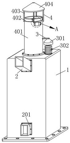
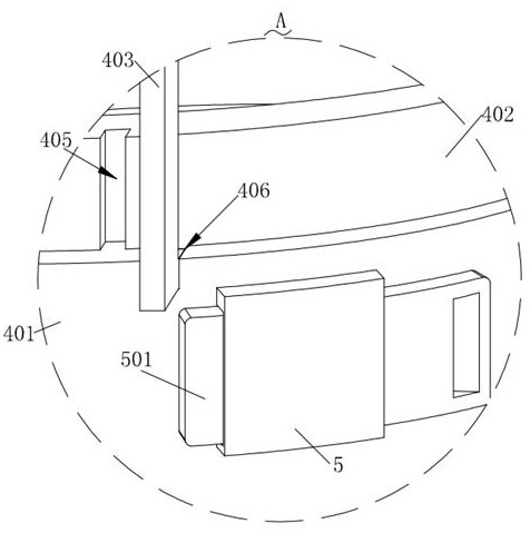
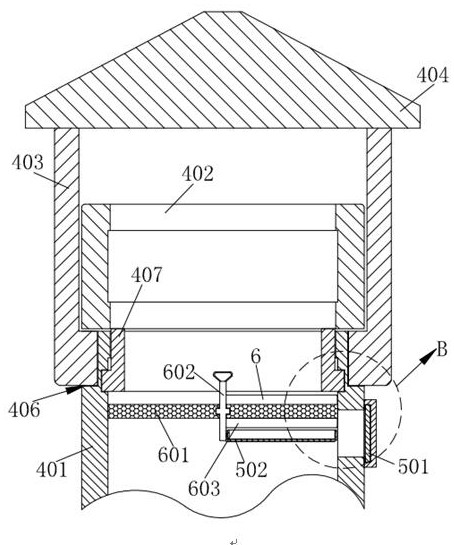
[0032] Such as Figure 1-Figure 9 As shown, a coke oven flue gas treatment pipeline for dust removal, desulfurization and denitrification according to the present invention includes an outer pipeline 1, and a cooling mechanism 2 for cooling flue gas is installed on the outer pipeline 1, and the outer pipeline 1 A cleaning mechanism 3 for cleaning the ammonium bisulfate condensed on the cooling mechanism 2 is installed on the top, the cleaning mechanism 3 conflicts with the cooling mechanism 2, and a smoke exhaust mechanism 4 is installed on the outer pipeline 1, and the smoke exhaust mechanism 4 A dust scraping mechanism 6 for filtering particulate matter in the flue gas is installed on the top, and a collection mechanism 5 for collecting dust is i...


PUM


Abstract

The invention relates to the technical field of coke oven flue gas treatment pipelines, in particular to a coke oven flue gas treatment pipeline for dust removal, desulfurization and denitrification, which comprises an outer pipeline, a cooling mechanism for cooling flue gas is mounted on the outer pipeline, and a cleaning mechanism for cleaning ammonium bisulfate condensed on the cooling mechanism is mounted on the outer pipeline. The cleaning mechanism abuts against the cooling mechanism, a smoke discharging mechanism is installed on the outer pipeline, a dust scraping mechanism for filtering particulate matter in smoke is installed on the smoke discharging mechanism, and a collecting mechanism for collecting dust is installed on the dust scraping mechanism. The cooling mechanism is mounted in the outer pipeline, and the cleaning mechanism for cleaning ammonium bisulfate condensed outside the cooling mechanism is mounted on the outer pipeline, so that when more ammonium bisulfate exists on the cooling mechanism, the cleaning mechanism can be started, particles of the ammonium bisulfate on the cooling mechanism are cleaned, and the heat exchange effect of flue gas is improved; and desulfurization and denitrification are facilitated.

Description

technical field [0001] The invention relates to the technical field of coke oven flue gas treatment pipelines, in particular to a coke oven flue gas treatment pipeline for dust removal, desulfurization and denitrification. Background technique [0002] Coking oven, a furnace usually made of refractory bricks and refractory blocks, is used to convert coal to produce coke, and a kiln for refining coke with coal is the main thermal equipment for coking. A modern coke oven refers to a horizontal chamber coke oven whose main purpose is to produce metallurgical coke and can recycle coking chemical products. Special flue gas treatment pipes are used for flue gas treatment and discharge. [0003] However, when the coke oven flue gas treatment pipeline used for dust removal, desulfurization and denitrification is exhausted, a cooling device is first installed inside the pipeline, and the flue gas is cooled through the internal cooling pipeline when the flue gas is discharged. Ammon...

Claims


Application Information

Patent Timeline
Patent Type & Authority Applications(China)
IPC IPC(8): F27D17/00B01D46/10B01D46/42B01D46/681B01D46/88
CPCF27D17/004F27D17/008B01D46/10B01D46/42B01D46/4218
Inventor 宋学凯卢胜华睢辉张延春吕丽慧郭芮
Owner SHANDONG LAIGANG ENERGY SAVING ENVIRONMENTAL PROTECTION ENG
Why Eureka
Try Eureka