Separation and recovery device based on waste cable

A technology for the separation and recycling of waste cables, applied to circuits, electrical components, etc., can solve problems such as air pollution, easily damaged wire cores, and reduced recycling quality, and achieve the effects of improving recycling quality, improving winding efficiency, and improving work efficiency

Pending Publication Date: 2022-05-13
高国恩
View PDF0 Cites 0 Cited by
  • Summary
  • Abstract
  • Description
  • Claims
  • Application Information

AI Technical Summary

Problems solved by technology

[0002] In the process of recycling cables after they are discarded, the sheath is usually disposed of by incineration, and a large amount of rubber or plastic is incinerated to produce smoke containing various harmful substances, thereby polluting the air, and the sheath will not be destroyed. Recycle properly
Therefore, many researchers are currently paying attention to environmentally friendly cables. This type of cable mainly uses new materials and new layered materials for the cable sheath, and combines some inorganic non-metallic materials and some metal wires with specific rubber, and at the same time cooperates with core materials and sheaths. Reasonable collocation greatly strengthens the corrosion resistance and life of the cable sheath, thereby greatly improving the overall life of the cable as a whole. At the same time, when this part of the cable is recycled, even if it is incinerated, the pollution to the atmosphere is greatly reduced. , the existing waste cable separation and recovery device, when cutting the outer skin of the cable, because the cable is a flexible material, the cutting process can easily damage the inner core, which greatly reduces the recycling quality

Method used


Image

  • Separation and recovery device based on waste cable
  • Separation and recovery device based on waste cable
  • Separation and recovery device based on waste cable

Examples


Embodiment Construction

[0031] In describing the present invention, it should be understood that the terms "length", "width", "upper", "lower", "front", "rear", "left", "right", "vertical", The orientation or positional relationship indicated by "horizontal", "top", "bottom", "inner", "outer", etc. are based on the orientation or positional relationship shown in the drawings, and are only for the convenience of describing the present invention and simplifying the description, rather than Nothing indicating or implying that a referenced device or element must have a particular orientation, be constructed, and operate in a particular orientation should therefore not be construed as limiting the invention. Various embodiments of the present invention will be described in detail below in conjunction with the accompanying drawings.

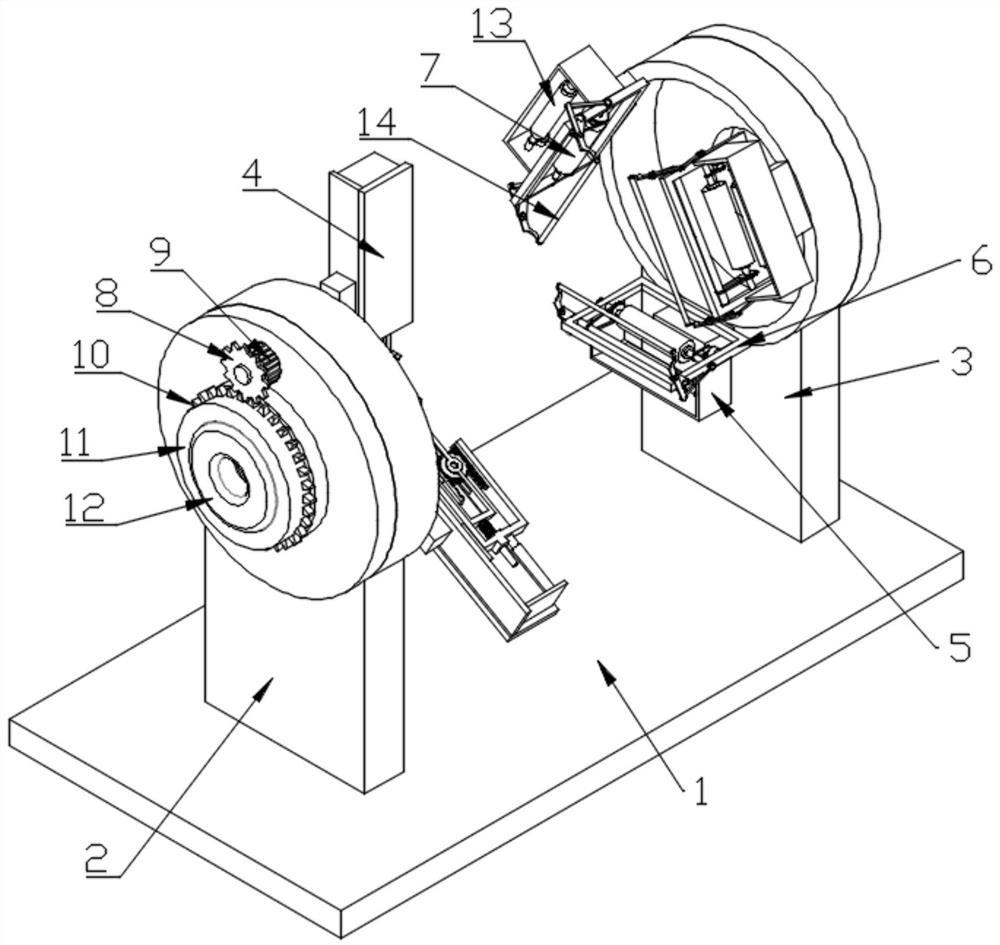
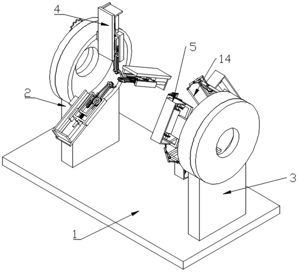
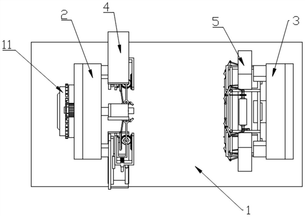
[0032] see Figure 1 to Figure 10 , the present invention provides a technical solution: a separation and recovery device based on waste cables, including a bottom plate 1, ...


PUM


Abstract

A waste cable-based separation and recovery device disclosed by the present invention comprises a bottom plate, the upper surface of the bottom plate is fixedly provided with a second support frame, the upper part of the second support frame is provided with a through groove for the waste cable to pass through, and a plurality of skin stripping mechanisms are annularly arrayed on the side wall of the second support frame where the through groove is located. Each skin stripping mechanism comprises a first fixing frame fixed to the side wall of the second supporting frame, and a movable block capable of sliding is installed in each first fixing frame. Through the structural design of the skin stripping mechanism, after three annularly arranged cutting blades are inserted into the skin of a waste cable, the skin of the waste cable can be rapidly stripped through the cutting effect of the three cutting blades, and meanwhile, due to the pre-fixing of an abutting block and the cutting arrangement of the cutting blades, the cutting efficiency of the waste cable is improved. And the possibility that the wire core is scratched can be effectively reduced, so that the recovery quality is further improved.

Description

technical field [0001] The invention relates to the technical field of cable recycling, in particular to a separation and recycling device based on waste cables. Background technique [0002] In the process of recycling cables after they are discarded, the sheath is usually disposed of by incineration, and a large amount of rubber or plastic is incinerated to produce smoke containing various harmful substances, thereby polluting the air, and the sheath will not be destroyed. Recycle properly. Therefore, many researchers are currently paying attention to environmentally friendly cables. This type of cable mainly uses new materials and new layered materials for the cable sheath, and combines some inorganic non-metallic materials and some metal wires with specific rubber, and at the same time cooperates with core materials and sheaths. Reasonable collocation greatly strengthens the corrosion resistance and life of the cable sheath, thereby greatly improving the overall life of...

Claims


Application Information

Patent Timeline
IPC IPC(8): H01B15/00
CPCH01B15/00H01B15/005
Inventor 高国恩
Owner 高国恩
Why Eureka
Try Eureka