Battery series-parallel connection switching main circuit, system and method without power output interruption

A main circuit and circuit technology, applied in the field of circuit devices, can solve the problems of contact erosion, arc flashover erosion, high current impact, etc., achieve good power acceleration performance and driving experience, and eliminate arc flashover and burning. Corrosion, eliminate the effect of high current impact

Active Publication Date: 2022-05-17
贺洪芝
View PDF7 Cites 0 Cited by
  • Summary
  • Abstract
  • Description
  • Claims
  • Application Information

AI Technical Summary

Problems solved by technology

1. In the process of switching from the parallel connection state to the series connection, when the switch supporting the parallel connection is disconnected, the self-inductance current on the positive and negative pole lines of the power supply between the battery and the motor controller has no freewheeling circuit, resulting in the disconnection of each switch at the moment of disconnection. A high overshoot voltage is generated at both ends, which is likely to cause arc flashover and erosion between contacts or overvoltage breakdown of semiconductor non-contact switches; 2. It takes a long time for the relay to receive the closing instruction signal to contact closing. After the switch that supports parallel connection is disconnected, it takes a long time for the switch that supports series connection to complete the contact closure. If the electric vehicle is in the acceleration condition from low speed to highest speed at this time, it corresponds to the motor from low speed to high speed. During the load acceleration phase of the load, the power output of the battery pack is interrupted during the period after the switch that supports parallel connection is turned off and before the switch that supports series connection is closed. During this period, the voltage of the DC bus support capacitor of the motor controller drops rapidly. It will cause no power output to the motor controller, and then the power of the electric drive system or the vehicle will be interrupted when accelerating, which will have a great negative impact on the vehicle's power performance and driving experience; 3. Existing The three-relay main circuit technical solution cannot solve the problem of large current impact when the battery pack outputs drive power to the motor controller from parallel to series.
When the switch supporting series connection is closed, since there is a huge voltage difference between the DC bus support capacitor voltage and the battery pack voltage connected in series, once the switch supporting series connection is forcibly closed, there will be a gap between the battery pack and the above DC bus support capacitor. A large inrush current is generated in the circuit between them. When the switch that supports series connection is closed, it will cause local high heat in the contact area or even arc flashover and erosion on the two contact contacts of the relay, which greatly affects the reliability and reliability of contact contact. At the same time, excessive inrush current has an adverse effect on the above-mentioned DC bus support capacitors and batteries, and high current change rates or arcs will cause electromagnetic interference to peripheral circuits

Method used


Image

  • Battery series-parallel connection switching main circuit, system and method without power output interruption
  • Battery series-parallel connection switching main circuit, system and method without power output interruption
  • Battery series-parallel connection switching main circuit, system and method without power output interruption

Examples


Embodiment Construction

[0087] The formation and use of some embodiments will be described in detail below in conjunction with the accompanying drawings. The embodiments described herein with respect to the accompanying drawings are illustrative, diagrammatic and are used to provide a basic understanding of the invention. The specific embodiments described are merely illustrative of specific ways to make and use the invention, and do not limit the scope of the invention.

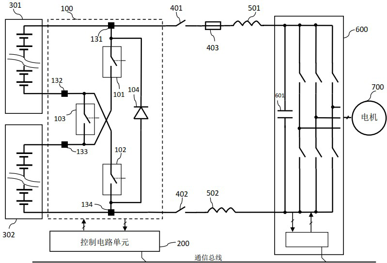
[0088] In the embodiment of the present invention figure 1 middle, figure 1 The shown series-parallel switching main circuit 100 is the basis of the present invention, and the main circuit 100 includes:

[0089] the first battery positive terminal 131, which is electrically coupled to the positive terminal of the first battery module 301;

[0090] the first battery negative terminal 132, which is electrically coupled to the negative terminal of the first battery module 301;

[0091] the second battery positive terminal 133, whi...


PUM


Abstract

The invention relates to the field of circuit devices for battery pack power supply, and provides a battery series-parallel connection switching main circuit, system and method without power output interruption. When the two battery modules output power to an electric driving system comprising a motor controller and a motor, the main circuit and the method can perform series-parallel switching without power interruption, so that the problem of power interruption during switching of a switching circuit mainly comprising three relays is solved; the main circuit comprises a first battery positive port, a first battery negative port, a second battery positive port, a second battery negative port, a first switch electrically coupled between the first battery positive port and the second battery positive port, and a second switch electrically coupled between the second battery negative port and the first battery negative port. The diode is electrically coupled between the first battery positive port and the second battery negative port; and the semiconductor contactless switch is electrically coupled between the first battery negative port and the second battery positive port.

Description

technical field [0001] The invention relates to a circuit device for power supply of a battery pack, in particular to a circuit and method for battery series-parallel switching without power output interruption, and a battery pack, an electric propulsion system and a vehicle using the circuit or method. Background technique [0002] In order to realize the fast charging function, electric vehicles need greater charging power, but the greater charging power is limited by the maximum charging current of the 400V voltage platform and cannot meet the needs of fast charging time, so electric vehicles with 800V voltage platform came into being. and meet the needs of fast charging. However, due to the lag in the construction of 800V fast charging basic charging facilities, the coverage network cannot meet the demand. Therefore, electric vehicles with 800V voltage platform need charging piles with 400V voltage platform to be able to charge them when there is no fast charging pile wi...

Claims


Application Information

Patent Timeline
Patent Type & Authority Applications(China)
IPC IPC(8): B60L50/60B60L50/40B60L3/00
CPCB60L50/60B60L50/40B60L3/0023Y02T90/12
Inventor 贺洪芝
Owner 贺洪芝
Why Eureka
Try Eureka