
Multi-element composite aerosol atomization device

An atomization device and aerosol technology, applied in the field of tobacco, etc., can solve the problems of low production efficiency, single taste, poor tobacco taste and mouthfeel simulation, and achieve the effect of increasing production efficiency and reducing production cost

Pending Publication Date: 2022-05-20
YUNNAN XIKE TECH CO LTD
View PDF0 Cites 0 Cited by
  • Summary
  • Abstract
  • Description
  • Claims
  • Application Information

AI Technical Summary

Problems solved by technology

[0006] 1. The scope of use of spices in the existing electric heating atomization device is relatively narrow, and it cannot be used for spices with high sugar content and poor solubility of PG and VG. The atomization chip at 200-300 ° C can release the aroma of many compound spices Relatively limited, the simulation degree of atomized aerosol on the taste and mouthfeel of tobacco is poor
[0007] 2. The existing aerosol generation matrix uses air as the carrier of aerosol transfer, so the working temperature is limited and can only be heated within 300°C. Although it has advantages in aroma release and tobacco aerosol simulation, the aerosol Insufficient amount of sol is a technical difficulty for aerosol-generating substrates
[0008] 3. In the prior art, whether it is a heating aerosol generating device or an electric heating atomizing device, the taste is very single, and it can only be filled with an aerosol generating matrix with one flavor.
[0009] Existing aerosol-generating products, in order to prevent the movement of the aerosol matrix segment, and the aerosol temperature is too high, it is necessary to install components such as barrier diversion and cooling, which makes the production process more complex, high production cost, and low production efficiency

Method used


Image

  • Multi-element composite aerosol atomization device
  • Multi-element composite aerosol atomization device
  • Multi-element composite aerosol atomization device

Examples


Embodiment 1

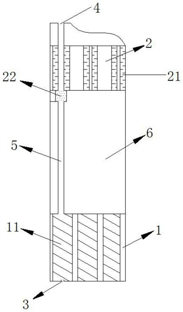
[0043] This embodiment provides a multi-component composite aerosol atomizing device, which includes a heating aerosol generating unit 1, an electric heating atomizing unit 2, an air inlet 3, a suction nozzle 4, an airway guide unit 5, a power supply and an electric Control unit 6 ; the heated aerosol generating unit 1 and the electrically heated atomizing unit 2 are in gas communication through the air channel guide unit 5 .

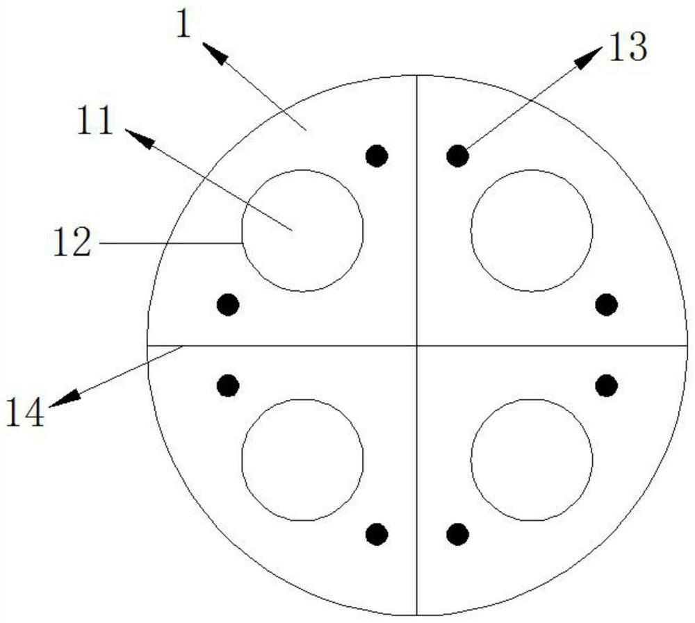
[0044] The heated aerosol generating unit 1 includes a plurality of aerosol generating substrate accommodating chambers 11, and the heated aerosol generating unit 1 can move with respect to the multi-component composite aerosol atomizing device, so as to accommodate different aerosol generating substrates. The cavity 11 is opposite to the airway guide unit 5; and / or, the electrically heated atomization unit 2 includes a plurality of atomization substrate accommodating cavities 21, and the electrically heated atomization unit 2 can be used for the multi-c...

Embodiment 2

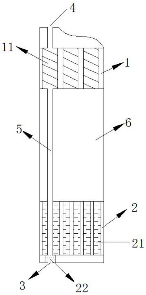
[0049] The difference between the multi-component composite aerosol atomizing device of this embodiment and the embodiment 1 is that the electrically heated atomizing unit 2 is located upstream of the heated aerosol generating unit 1, and the gas enters through the air inlet 3, and then passes through the The electrically heated atomizing unit 2 , the air channel guide unit 5 , and the heated aerosol generating unit 1 flow out through the suction nozzle 4 . In this case, the heating aerosol generating unit 1 is not provided with a separate heating component, and the atomized aerosol generated by the electrically heated atomizing unit 2 is eluted from the heating aerosol generating unit 1 and then flows out through the suction nozzle 4 .


PUM


Abstract

The invention discloses a multi-element composite aerosol atomization device, which comprises a heating aerosol generation unit (1), an electric heating atomization unit (2), an air inlet (3), a suction nozzle (4), an air passage diversion unit (5), a power supply and an electric control unit (6), the heating aerosol generating unit (1) and the electric heating atomization unit (2) are in gas communication through the gas channel flow guide unit (5). According to the multi-element composite aerosol atomization device, the suction atomization matrix and the aerosol generation matrix are compounded, the problems that particulate matter of an electric heating atomization device is insufficient, the difference between atomized aerosol and combustion aerosol is large, and the aerosol amount of a heating type aerosol generation device is small are solved. In addition, aerosol generating matrixes, atomizing matrixes and aroma enhancing matrixes with different tastes can be freely matched through a disc type rotary filling structure, and matching of the different tastes is freely combined.

Description

technical field [0001] The invention relates to the fields of low-temperature heating type aerosol generating devices and electric heating atomizing devices, in particular to a multi-component composite aerosol atomizing device. Background technique [0002] The electric heating atomization device atomizes the solution containing nicotine and essence into particles through airflow induction and the chip is heated at 200-300 ℃, which is absorbed through the lungs and exhales simulated smoke at the same time. [0003] The aerosol-generating substrate is heated by a special heating source at 280-330°C. During heating, the aroma substances in the aerosol-substrate segment are volatilized to generate aerosols to meet the needs of users. The aerosol matrix segment of the inhalation sol generating matrix is ​​in a non-combustion state, so that harmful components produced by high temperature combustion and cracking of tobacco can be reduced. [0004] The aerosol generation substrat...

Claims


Application Information

Patent Timeline
Patent Type & Authority Applications(China)
IPC IPC(8): A24F40/46A24F40/40A24F40/42A24F40/50A24F40/30
CPCA24F40/46A24F40/40A24F40/42A24F40/50A24F40/30
Inventor 尧珍玉邱智沈靖轩代云袁盛洪田孟鑫
Owner YUNNAN XIKE TECH CO LTD
Learn More