Novel remote adjusting device for concealed air valve
A technology of remote adjustment and air valve, which is applied in the direction of high-efficiency adjustment technology, climate sustainability, mechanical equipment, etc. It can solve the problems of poor overall perception quality of the ceiling, high failure rate of weak current control system, and high cost of analog air valve. , to achieve the effects of high construction efficiency, improved installation quality, convenient operation and use
- Summary
- Abstract
- Description
- Claims
- Application Information
AI Technical Summary
Problems solved by technology
Method used
Image
Examples
Embodiment 1
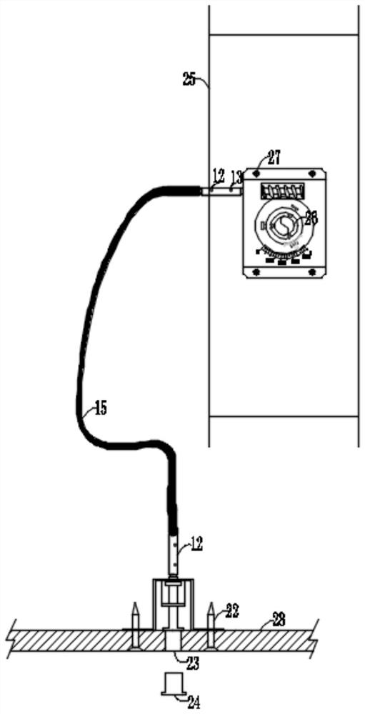
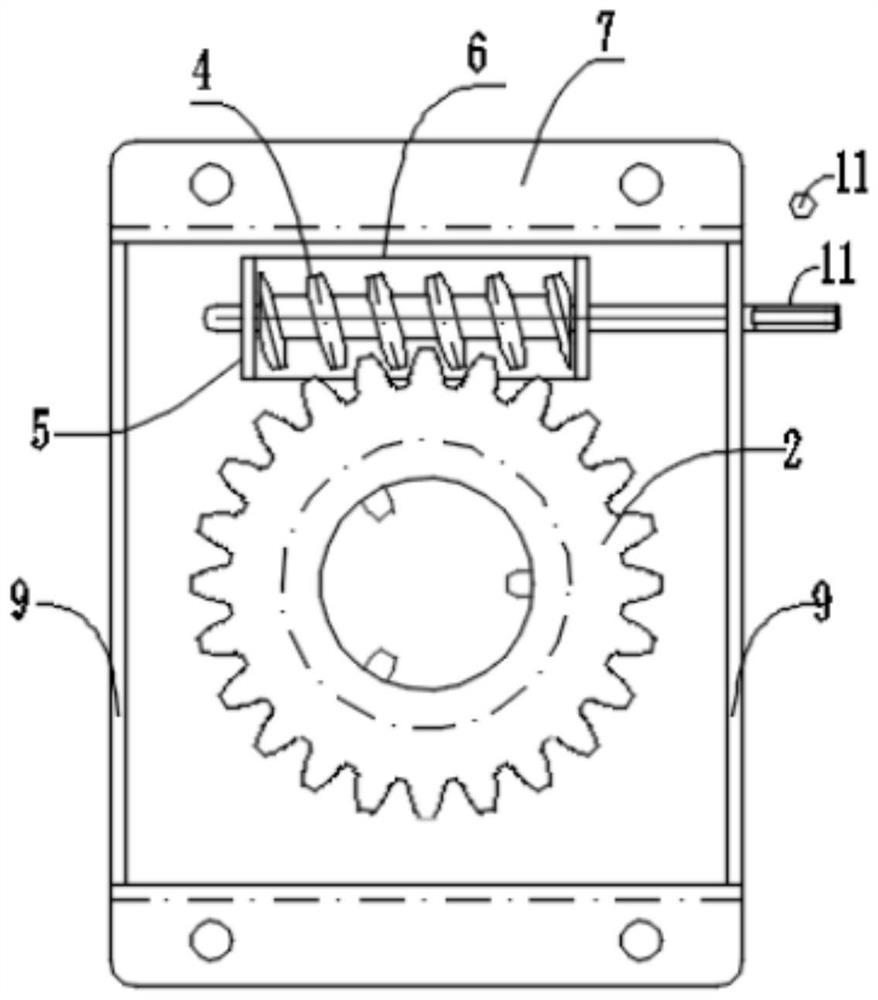
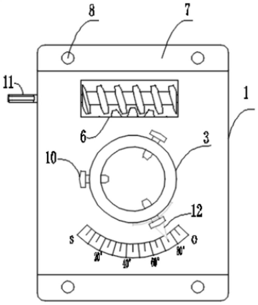
[0033] see Figure 1~6 , a new type of concealed air valve remote adjustment device, including
[0034] The actuator, which is made of steel material, is fixedly installed on the inner side wall of the air valve 25 for adjusting the opening angle of the air valve 25, and it includes a mechanism casing 1, a turbine 2 arranged in the mechanism casing 1 And the worm 4, the worm 4 is horizontally connected to the worm fixing plate 5 located in the mechanism housing 1, and is engaged with the worm gear 2, and the end of the worm gear 2 located outside the mechanism housing 1 is welded and fixed with a worm gear The shaft sleeve 3, and the inner cavity of the turbine shaft sleeve 3 is provided with the valve rod 26 of the air valve 25, and the end of the worm 4 protruding from the outer side of the mechanism casing 1 is fixedly connected with the worm drive connector 11.
[0035] In the embodiment of the present invention, the mechanism casing 1 is provided with a hollow groove 6 a...
Embodiment 2
[0041] see Figure 7 , a new type of concealed air valve remote adjustment device, including
[0042] The flexible transmission assembly is made of steel material for mechanical transmission, and it includes a transmission steel wire shaft 15 and a transmission steel wire connecting headgear 16 located at both ends of the transmission steel wire shaft 15. The inside of the transmission steel wire shaft 15 is a multi-strand The steel wire rope is coated with a PVC sheath on the outside. The transmission steel wire connection head cover 16 at one end of the transmission steel wire shaft 15 is set on the worm drive connection head 11, and the transmission steel wire connection head cover 16 at the other end of the transmission steel wire shaft 15 is set at the operating position. On the shaft of the operating mechanism transmission rod 18 on the outside of the mechanism housing 17.
[0043]In the embodiment of the present invention, a regular hexagonal groove 14 is opened in the...
Embodiment 3
[0045] see Figure 8-9 , a new type of concealed air valve remote adjustment device, including
[0046] The operating mechanism is made of steel material, and is fixedly installed on the hanging cabinet plate 28 for the operator to perform manual operation, and it includes an operating mechanism casing 17, an operating mechanism transmission that is rotatably connected in the operating mechanism casing 17 Rod 18, the operating mechanism transmission rod limiting plate 19 that is sleeved on the body of the operating mechanism transmission rod 18 is installed in the operating mechanism housing 17, and the operating mechanism transmission rod 18 passes through the through hole provided by the operating mechanism housing 17 The shaft of the shaft is provided with an operating mechanism transmission rod limit ring 20.
[0047] In the embodiment of the present invention, two sides of the operating mechanism casing 17 are provided with operating mechanism fixing holes 21 for passing...
PUM
 Abstract
Description
Claims
Application Information
 - R&D
- Intellectual Property
- Life Sciences
- Materials
- Tech Scout
- Unparalleled Data Quality
- Higher Quality Content
- 60% Fewer Hallucinations
Browse by: Latest US Patents, China's latest patents, Technical Efficacy Thesaurus, Application Domain, Technology Topic, Popular Technical Reports.
© 2025 PatSnap. All rights reserved.Legal|Privacy policy|Modern Slavery Act Transparency Statement|Sitemap|About US| Contact US: help@patsnap.com


