Rail transit line integrated design method and system

A rail transit and design method technology, applied in the field of rail transit, can solve the problems of high technical ability requirements for designers, low level of tool automation, high business technical ability, etc., to reduce the amount of investment, improve the level of design automation, and reduce the design cost. Effect of Difficulty and Designer's Business Capability Requirements

Pending Publication Date: 2022-05-20
浙江众合科技股份有限公司
View PDF0 Cites 0 Cited by
  • Summary
  • Abstract
  • Description
  • Claims
  • Application Information

AI Technical Summary

Problems solved by technology

[0003] The disadvantages of traditional rail transit wiring design are as follows: multiple tools are used in the process of line design and generation, and designers need to master the skills of using multiple tools, or multiple people participate in the design, and the design efficiency is low; the input of the next design process cannot be directly used The output of the previous design process requires the designer to manually convert the format. For example, the "line data generation tool" cannot read the line plan output by the "CAD tool", and the designer needs to manually edit the "line data generation tool" according to the line plan. The circuit topology structure increases the design workload; the tool automation level is low, and the technical ability of the designer is too high. For example, the design principle and the route table generation require high business technical ability

Method used


Image

  • Rail transit line integrated design method and system
  • Rail transit line integrated design method and system
  • Rail transit line integrated design method and system

Examples


Embodiment

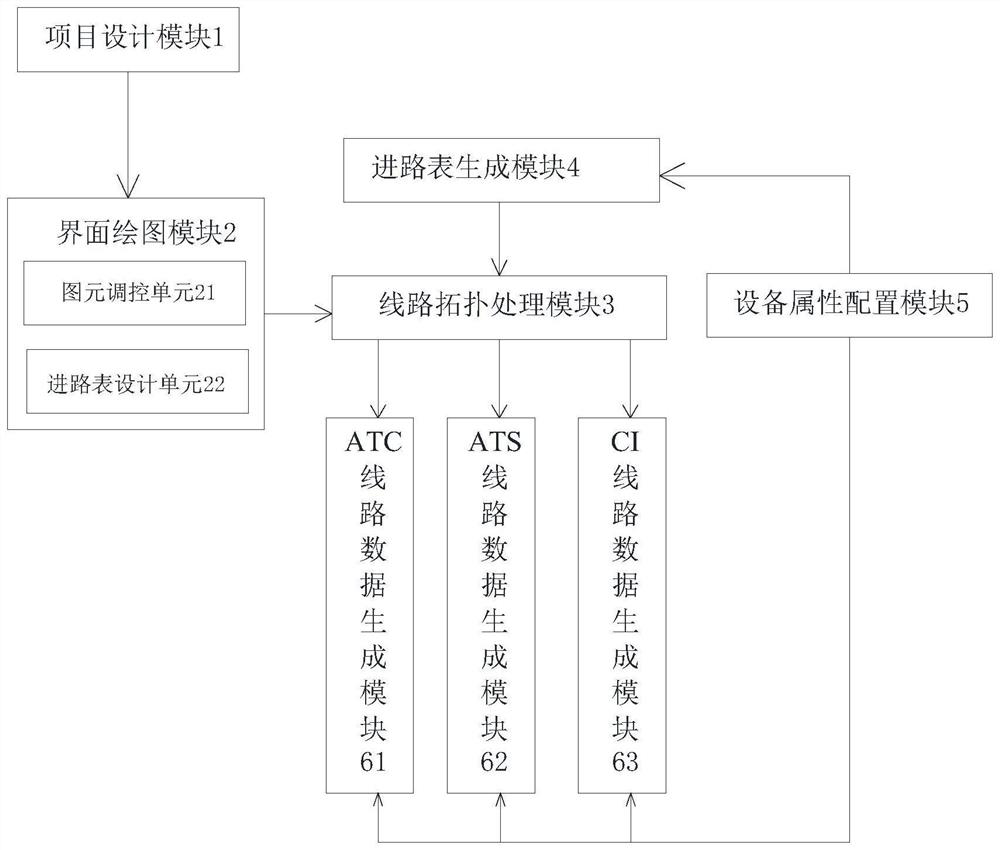
[0029] Example: such as figure 1 As shown, a rail transit line integrated design method includes the following steps:

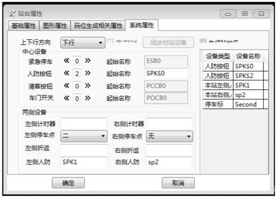
[0030] The interface drawing module 2 obtains the track line attribute information in the project design module 1 to draw a rail transit plane map; calls the corresponding equipment graphic elements through the graphic element control unit to fill and mark the track line attribute information;

[0031] Set the route information in the rail transit plane map through the route table design unit;

[0032] After the rail transit planar map is drawn, the line topology processing module 3 obtains the track line attribute information and route table information of the rail transit planar map to generate the logical topology of the device;

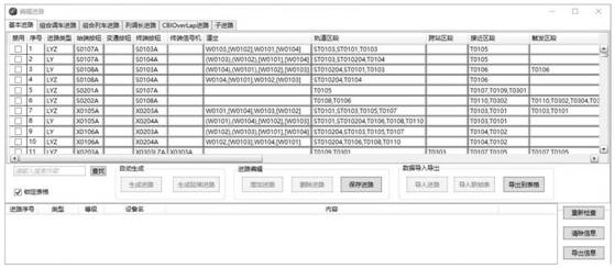
[0033] Route table generating module 4 searches for the logic topology data of the equipment on the whole line, and generates the route table format data respectively with the interlocking centralized station as the subunit of a...


PUM


Abstract

The invention discloses a rail transit line integrated design method and system. The method comprises the following steps that an interface drawing module obtains rail line attribute information in a project design module to draw a rail transit plane map; corresponding equipment primitives are called through a primitive regulation and control unit to fill and label track line attribute information; setting route information in the rail transit plane map through a route table design unit; the line topology processing module is used for acquiring track line attribute information and route table information of a track traffic plane map to generate an equipment logic topology structure; the route table generation module searches for whole-line equipment logic topological structure data and generates route table type data; the line data generation module constructs a subdata formatted file; and a designer exports a data formatted file and route table type data to realize a line design integrated process. By combining multiple tools, a data link is broken through, manual data format conversion work is omitted, and the design automation level is further improved.

Description

technical field [0001] The present invention relates to the technical field of rail transit, in particular to an integrated design method and system for rail transit lines. Background technique [0002] The steps of traditional rail transit wiring design are as follows: First, the designer uses "CAD tool" to draw the line plan according to the design principle and civil engineering data. According to the route plan, the personnel calculate the route parameters through the "route table design tool", including: the length of the approach section, the unlocking time of the route, the unlocking time of the protection section, etc.; secondly, the designer uses the "Office tool" to add Relevant equipment and corresponding mileage marks are converted into an excel form, and equipment attributes are configured; finally, the designer uses the "line data generation tool" to draw the line topology, and imports information such as equipment mileage marks and equipment attributes, and au...

Claims


Application Information

Patent Timeline
IPC IPC(8): G06F30/12G06F30/20G06F9/451
CPCG06F30/12G06F30/20G06F9/451Y02P90/02
Inventor 郑木火刘爱军宗永胜罗丹吴松野
Owner 浙江众合科技股份有限公司
Why Eureka
Try Eureka