Rotary variable-rigidity variable-damping vibration attenuation boring bar
A variable stiffness and variable damping technology, applied in the field of rotary variable stiffness variable damping vibration damping boring bars, can solve the problems of machining accuracy and machining efficiency, and achieve the effect of improving machining efficiency and machining accuracy.
- Summary
- Abstract
- Description
- Claims
- Application Information
AI Technical Summary
Problems solved by technology
Method used
Image


Examples
specific Embodiment approach 1
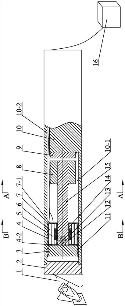
[0025] Specific implementation mode one: combine Figure 1 to Figure 5 Describe this embodiment, a rotary variable stiffness variable damping vibration reduction boring bar described in this embodiment includes a cutter head connection block 2, a stepping motor 3, a casing 4, an electromagnet 9, a shaft 10, a support sleeve 11, Sleeve 14, rectangular cantilever beam 15, control system 16 and multiple brake components, the middle part of the front end of the shaft 10 is provided with a boring bar cavity 10-1, and the rear end of the cutter head connecting block 2 is inserted into the boring bar In the cavity mouth of the cavity 10-1, the support sleeve 11 is inserted into the front end of the boring bar cavity 10-1, the stepper motor 3 is fixedly connected to the inner side wall of the front end of the support sleeve 11, and the output shaft of the stepper motor 3 It is affixed to the front end of the rectangular cantilever beam 15, the sleeve 14 is set on the front end of the ...
specific Embodiment approach 2
[0034] Specific implementation mode two: combination Figure 1 to Figure 5 This embodiment is described. The rear end of the rectangular cantilever beam 15 in this embodiment is sleeved and fixed to the mass block 8 . Other compositions and connection methods are the same as those in Embodiment 1.
[0035] The mass block 8 designed in this way increases the corresponding area between the rectangular cantilever beam 15 and the electromagnet 3 9 on the one hand, and has the effect of counterweight on the other hand, increases the weight of the rear end of the rectangular cantilever beam 15 and reduces the weight of the rectangular cantilever beam 15 itself. vibration.
specific Embodiment approach 3
[0036] Specific implementation mode three: combination Figure 1 to Figure 5 To describe this embodiment, the front cover 4 - 2 is fixedly connected to the front end surface of the casing 4 in this embodiment, and the casing cover 7 is fixedly connected to the rear end surface of the casing 4 . Other compositions and connection methods are the same as those in the second embodiment.
[0037] Such a design facilitates the installation of the brake assembly.
[0038] The housing cover 7 is provided with a through hole 7-1, and the through hole 7-1 is used for connecting wires to pass through.
PUM
 Abstract
Description
Claims
Application Information
 - R&D
- Intellectual Property
- Life Sciences
- Materials
- Tech Scout
- Unparalleled Data Quality
- Higher Quality Content
- 60% Fewer Hallucinations
Browse by: Latest US Patents, China's latest patents, Technical Efficacy Thesaurus, Application Domain, Technology Topic, Popular Technical Reports.
© 2025 PatSnap. All rights reserved.Legal|Privacy policy|Modern Slavery Act Transparency Statement|Sitemap|About US| Contact US: help@patsnap.com