
Integrated hot blast stove

A hot blast stove and integrated technology, which is applied in the field of integrated hot blast stoves, can solve problems such as increased impact probability, low energy utilization rate, and increased air density, and achieve the effects of reducing heat waste, slowing down heat loss, and improving cleanliness

Pending Publication Date: 2022-05-27
福建中闽绿康环保设备有限公司
View PDF1 Cites 0 Cited by
  • Summary
  • Abstract
  • Description
  • Claims
  • Application Information

AI Technical Summary

Problems solved by technology

[0003] The energy generated by the combustion of the hot blast stove is certain, and it is crucial to make full use of the energy generated by it. However, the energy generated by the combustion of the existing hot blast stove heats the heat pipe, and the heat of the heat pipe is taken away by blowing. The energy utilization rate is low, at 30%-40%, and a small amount of hot blast stoves with high energy utilization rate mostly change the internal structure of the hot blast stove, which is expensive
The existing patent application number 202011317539.1 discloses an energy-saving hot air stove, which is equipped with a blower on the top of the combustion chamber, and the cold air generated by the blower pressurizes the wind blown by the blower, so that the density of the wind becomes larger, and the conduction pressure of the wind is The impact probability of the furnace wall is increased, thereby absorbing more energy, and the thermal efficiency utilization rate is high, achieving the effect of energy saving and emission reduction. It is worth promoting, but it still needs to be improved

Method used


Image

  • Integrated hot blast stove
  • Integrated hot blast stove
  • Integrated hot blast stove

Examples


Embodiment Construction

[0026] The present invention will now be further described with reference to the accompanying drawings and specific embodiments.

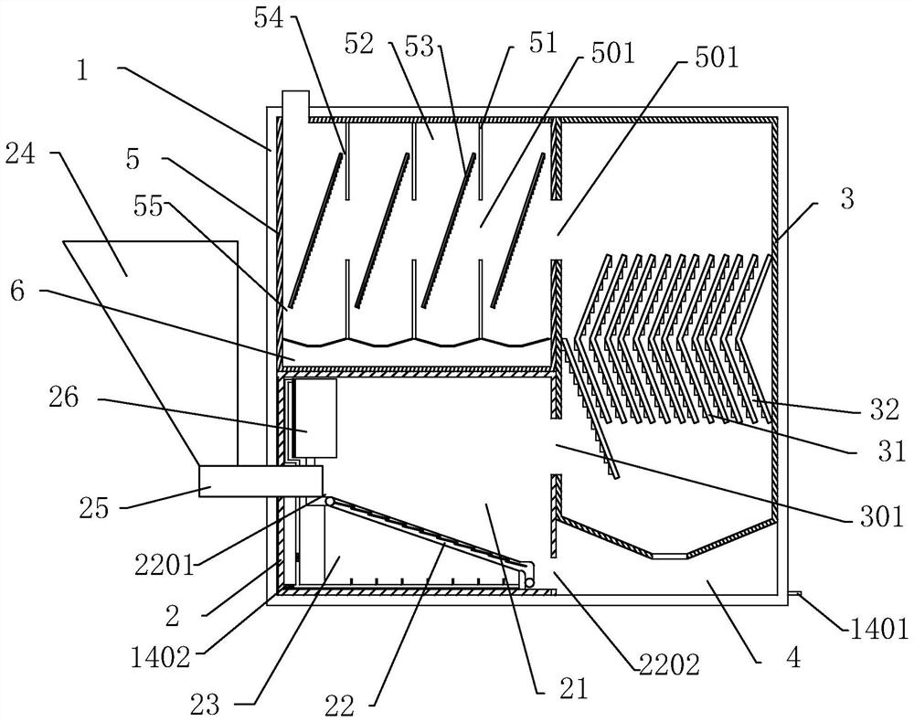
[0027] refer to Figure 1 to Figure 8 , This embodiment provides an integrated hot blast stove, including a casing 1, and the casing 1 is provided with a combustion chamber 2, a primary ash chamber 3 and a secondary ash chamber 5.

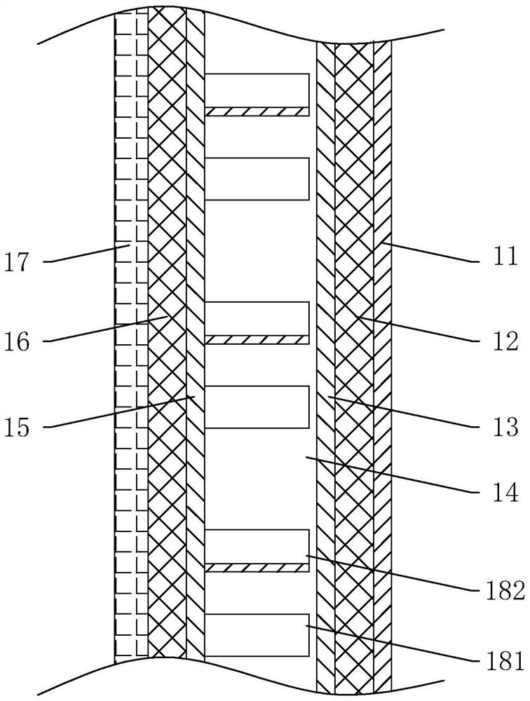
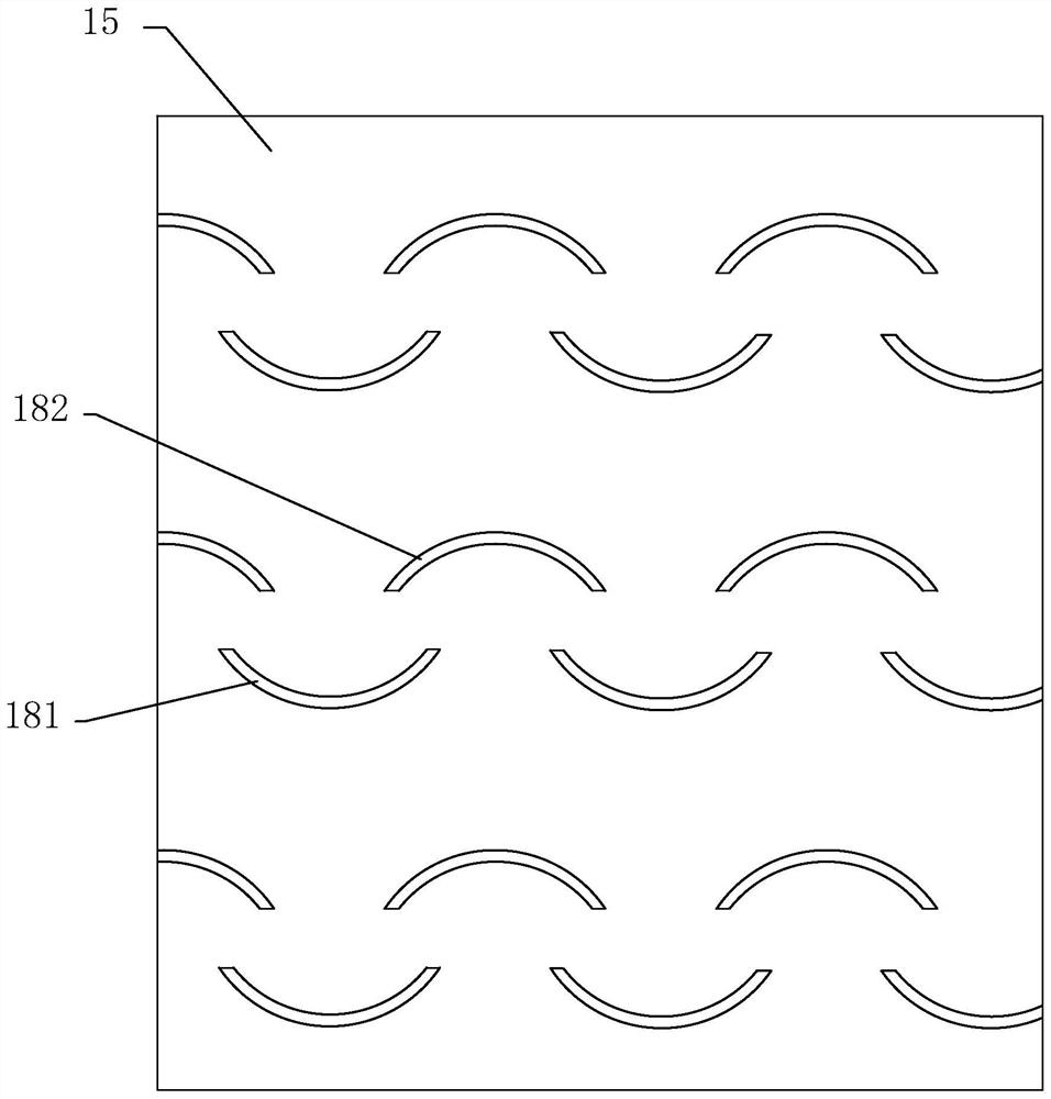
[0028] The casing 1 includes a decorative panel 11, an outer thermal insulation layer 12, an outer panel 13, a cold air passage 14, a middle panel 15, an inner thermal insulation layer 16 and an inner panel 17 in sequence from the outside to the inside, and the cold air passage 14 is provided with an air inlet 1401 and an air outlet 1402, the air inlet 1401 is connected to an external fan, and the cold air passage 14 is provided with a plurality of sets of heat dissipation components at intervals from the air inlet 1401 to the air outlet 1402 on the middle plate 15. The first heat dissipation plate 181 and the second h...


PUM


Abstract

The integrated hot blast stove comprises a shell, a combustion chamber, a first-stage ash discharge chamber and a second-stage ash discharge chamber are arranged in the shell, the combustion chamber is built by refractory bricks and comprises a hearth, a fire grate and an air chamber, the fire grate is provided with a feeding port and an ash discharge port, the first-stage ash discharge chamber is arranged on one side of the hearth, and the second-stage ash discharge chamber is arranged on the other side of the hearth. A first air opening is formed between the hearth and the first-stage ash discharging chamber, a first-stage settling chamber is arranged below the first-stage ash discharging chamber, a plurality of first ash blocking plates are arranged in the first-stage ash discharging chamber, the second-stage ash discharging chamber is arranged on one side of the first-stage ash discharging chamber, the first-stage ash discharging chamber is provided with a second air opening communicated with the second-stage ash discharging chamber, and the second air opening is communicated with the second-stage ash discharging chamber. The secondary ash discharging chamber is divided into a plurality of blocking chambers through blocking walls, a secondary settling chamber is arranged below each blocking chamber, each blocking wall is provided with a ventilation hole, an inclined plate is arranged in each blocking chamber, and ash blocking protrusions are sequentially arranged on the lower surface of each inclined plate from top to bottom. The heat production efficiency of the hot-blast stove is effectively improved.

Description

technical field [0001] The invention relates to the technical field of hot blast stoves, in particular to an integrated hot blast stove. Background technique [0002] The hot blast stove was widely used in my country in the late 1970s, and it has become a replacement product of electric heat source and traditional steam power heat source in many industries. Some of the existing hot blast stoves still use coal as raw material. With the country's emphasis on energy conservation and environmental protection, biomass pellet fuel has almost zero emissions compared with coal, so the use of biomass pellet fuel for hot blast stove fuel has become the mainstream trend. [0003] The energy generated by the combustion of the hot blast stove is certain, and it is crucial to make full use of the energy generated by the combustion of the hot blast stove. However, the energy generated by the combustion of the existing hot blast stove heats the heat pipe, and the heat of the heat pipe is ta...

Claims


Application Information

Patent Timeline
Patent Type & Authority Applications(China)
IPC IPC(8): F22B31/00F22D5/34F23B40/00F23J1/02F23K3/14
CPCF23B40/00F23J1/02F22D5/34F22B31/00F23K3/14Y02B40/00
Inventor 肖阳
Owner 福建中闽绿康环保设备有限公司
Learn More