Broadband wide-angle scanning dual-band common-aperture phased-array antenna

A phased array antenna and wide-angle scanning technology, which is applied in the directions of individually powered antenna arrays, independent antenna unit combinations, antennas, etc. Sparse and other problems, to achieve the effect of improving broadband impedance matching ability, improving active standing wave performance, and overcoming narrow bandwidth

Pending Publication Date: 2022-05-27
CHINA ELECTRONIC TECH GRP CORP NO 38 RES INST
View PDF2 Cites 0 Cited by
  • Summary
  • Abstract
  • Description
  • Claims
  • Application Information

AI Technical Summary

Problems solved by technology

[0010] The technical problem to be solved by the present invention is how to solve the technical problems such as the relatively narrow bandwidth of the dual-band co-aperture antenna, which cannot meet the requirements of broadband scanning, sparse and irregular array, poor scalability, reconfigurability and engineering realization.

Method used


Image

  • Broadband wide-angle scanning dual-band common-aperture phased-array antenna
  • Broadband wide-angle scanning dual-band common-aperture phased-array antenna
  • Broadband wide-angle scanning dual-band common-aperture phased-array antenna

Examples


Embodiment 1

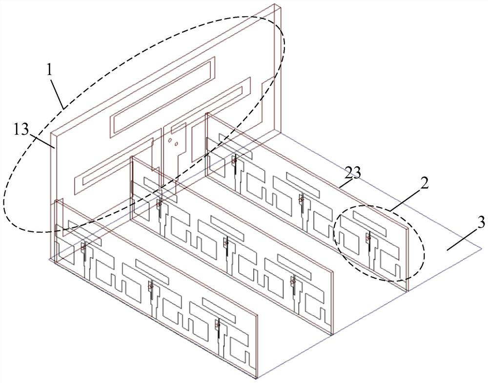
[0054] A dual-band common aperture phased array antenna unit with wide bandwidth angle scanning, the phased array antenna unit is composed of a low-band antenna unit, a high-band antenna unit and a metal reflector. The low-band antenna unit and the high-band antenna unit are in the form of vertical microstrip dipole antennas.

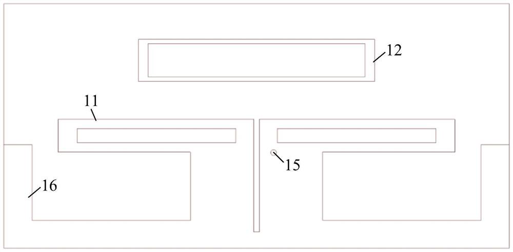
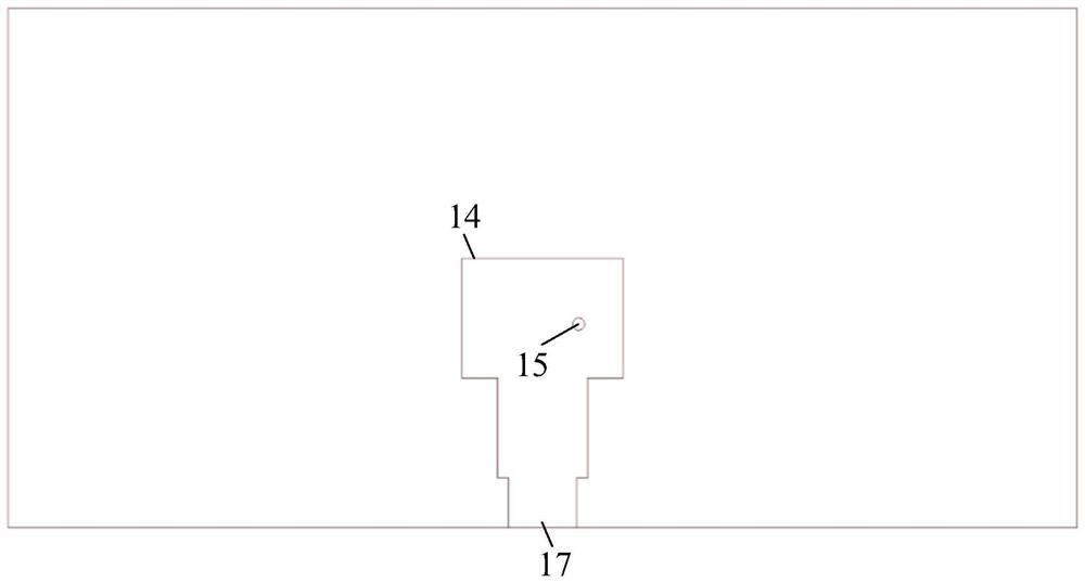
[0055] The low-frequency antenna unit is composed of radiating microstrip, parasitic patch, feeding microstrip, dielectric substrate, metal spacer bar, metallized through hole and coaxial feeding port; the low-frequency antenna unit is printed on a double-sided copper-clad dielectric substrate The front side of the dielectric substrate is a radiation microstrip and a parasitic patch, and the radiation microstrip and the parasitic patch are designed with a window. The reverse side of the dielectric substrate is the feeding microstrip, and the coaxial connector feeds the antenna unit through the coaxial feeding point on the feeding microstrip. The front ...

Embodiment 2

[0062] like Figure 7 As shown, in this embodiment, a dual-band common aperture phased array antenna array with wide bandwidth angle scanning is designed, and the phased array antenna array works in the S-band and the X-band.

[0063] The array is composed of periodic extension of common aperture phased array antenna elements. This embodiment includes: 64 units of S-band antenna units 8 (azimuth direction)×8 (elevation direction), and 576 units of X-band antenna units 24 (azimuth direction)×24 (elevation direction). The dielectric substrate used for S-band antenna unit 1 and X-band antenna unit 2 is Rogers 4350B with a relative permittivity of 3.66. The thickness of the dielectric substrate of S-band antenna unit 1 is 1.524mm, and the thickness of X-band antenna unit 2 is 0.508 mm. mm.

[0064] Figure 8 The active standing wave curves of the phased array antenna array of this embodiment at different scanning angles in the S-band are given, where f L0 Indicates the center ...


PUM


Abstract

The invention provides a broadband wide-angle scanning dual-band common-aperture phased-array antenna. The antenna comprises a low-band antenna unit, at least two high-band antenna units and a metal reflecting plate, the low-frequency-band antenna unit and the high-frequency-band antenna unit are vertically arranged on the metal reflecting plate in a crossed manner, and both the low-frequency-band antenna unit and the high-frequency-band antenna unit adopt vertical micro-strip oscillator antennas and adopt a profile unequal-height design; each low-frequency-band antenna unit comprises a radiation micro-strip, a parasitic patch and a metal isolation rod, the parasitic patch is loaded on the radiation micro-strip, and the metal isolation rod is arranged between the adjacent low-frequency-band antenna units; each high-frequency-band antenna unit comprises a radiation micro-strip and a parasitic patch, the parasitic patch is loaded on the radiation micro-strip, and the metal isolation rods are arranged between the adjacent high-frequency-band antenna units. The technical problems that the relative bandwidth of a dual-band common-caliber antenna is narrow, the broadband scanning requirement cannot be met, array arrangement is sparse and irregular, and expandability, reconfigurability and engineering realizability are poor are solved.

Description

technical field [0001] The invention belongs to the technical field of phased array antenna design, in particular to a dual-band common aperture phased array antenna with wide bandwidth angle scanning. Background technique [0002] The multi-function phased array radar is a high-performance phased array radar. One radar can realize the functions that can only be achieved by traditional multiple radars. The multi-function phased array radar completes the dual-band multi-function task of searching, tracking and identification through the comprehensive integration of frequency bands and system functions, and overcomes the defects of traditional single-band radar system architecture and single working mode. The new multi-function phased array radar with dual-band co-aperture working at the same time as a prominent feature requires the antenna to be in the form of dual-band co-aperture and capable of wide-bandwidth angular scanning. [0003] According to the prior art, there are...

Claims


Application Information

Patent Timeline
Patent Type & Authority Applications(China)
IPC IPC(8): H01Q21/30H01Q21/06H01Q19/10H01Q1/52H01Q1/50H01Q1/38
CPCH01Q21/30H01Q1/521H01Q1/523H01Q1/38H01Q1/50H01Q21/061H01Q21/065H01Q21/0006H01Q21/0075H01Q19/104
Inventor 严建杰赖清华高初喻宏伟
Owner CHINA ELECTRONIC TECH GRP CORP NO 38 RES INST
Why Eureka
Try Eureka