Electrically-driven three-stage planetary speed reduction driver

A three-stage planetary and planetary deceleration technology, applied in the direction of electric components, electromechanical devices, electrical components, etc., can solve the problems of large installation space, easily damaged gears, low assembly efficiency, etc., to reduce the thickness of gears, shorten the overall volume, The effect of improving assembly efficiency

Pending Publication Date: 2022-05-27
TIANJIN SNEIJDER PRECISION MACHINERY
1 Cites 0 Cited by

AI-Extracted Technical Summary

Problems solved by technology

However, most of the automatic flip gearboxes on the market have high friction between the motor, the reduction gearbox and its rotating shaft, the transmission ratio is high, the noise is loud, and the gears are easily damaged, resulting in a relatively low overall life of the gearbox (less than 10,000 times of opening and closing). , the failure rate of the product is high, and at the same time, the volume of the existing electric drive flip buffer is relatively large, and the installation takes up a large space
[0004] For this reason, the applicant has developed a smart home electric drive flip buffer with small size, large output torque, compact structure, low friction, low noise, stable operation, long service life, and quick opening and slow falling functions. For details, see, CN108980288A; however, the assembly efficiency of this kind of electric drive clamshell buffer is low in actual assembly, and there is still room for optimization in the overall structure, so as to further reduce frictional resistance, ensure relatively stable transmission parts, reduce noise, and prolong service life
[0005] Specifically, the prior art (CN108980288A) uses a three-stage planetary deceleration mechanism for electric drive flip buffers; when assembling, it is nec...

Method used

Further, the power shaft end of the drive motor is equipped with a motor flange, and the motor seal cover 10 is set on the motor flange, which plays a role in the protection of the drive motor, and extends the life of the driver under industrial and mining conditions such as humidity and dust. service life.
Please refer to Fig. 14 to Fig. 24, described three-stage planetary reduction unit 23 comprises three-stage planet carrier assembly 231, the three-stage planetary gear 232 installed in the three-stage planet carrier assembly; Wherein the three-stage planet carrier assembly It includes a three-stage rotary support plate 233 and an angle detection toothed plate 234. A three-stage planetary gear shaft 235 is installed between the three-stage rotary support plate and the angle detection tooth plate. The three-stage planetary wheel 235; on the three-stage rotary support plate 23 on the side away from the drive motor, a three-stage planetary wheel accommodation sleeve 236 is integrally provided, and an integrated structure is adopted. On the one hand, the number of parts is reduced, and the main purpose is three-stage The positions of the rotary support plate 23 and the three-stage planetary gear housing 236 are relatively fixed, thereby ensuring the position accuracy of the three-stage planetary gear installed therein and having the effect of sound absorption; the side walls of the three-stage planetary gear housing are provided with In the gap 237, the three-stage planetary wheel protrudes from the gap and meshes with the inner teeth of the ring gear housing; the angle detection tooth plate connecting column 238 is installed on the end surface of the supporting wall of the three-stage planetary wheel accommodating sleeve adjacent to the gap; the angle detection tooth plate connecting column is connected An angle detection toothed plate 234 ; the angle detection toothed plate is connected to the power output shaft 3 .
Please refer to Fig. 8 to Fig. 13; Described secondary planetary reduction unit 22, comprises secondary planetary carrier assembly 221, is installed in the secondary planetary gear 222 in secondary planetary carrier assembly; Wherein said secondary planetary carrier The assembly 221 includes a secondary rotary support disc 223, a secondary planetary wheel disc 224, and a secondary planetary shaft 225 integrally arranged on the secondary rotary support disc, which adopts an integrated design structure to ensure the accuracy of the installation position of the secondary planetary wheel; The other end of the first-stage planetary shaft is fixedly connected to the second-level planetary wheel disc, and the second-level planetary wheel disc is integrally provided with a second-level planetary wheel accommodation tube 226, and the second-level planetary wheel accommodation tube is provided with a second-level planetary wheel installation groove 227, The secondary planetary shaft 225 is located in the secondary planetary gear housing, and the secondary planetary gear 222 is installed on the secondary planetary shaft at the position of the secondary planetary gear installation groove; the secondary planetary gear meshes with the secondary sun gear 219 and the ring gear at the same time The inner teeth of the housing; the third-stage sun gear 228 is arranged at the center of the second-stage planetary wheel away from the drive motor side; after the assembly is completed, the second-stage planetary gear of the above-mentioned two-stage planetary reduction unit meshes with the second-stage sun gear, and meshes The inner teeth of the ring gear housing realize the two-stage deceleration of power, and drive the three-stage sun gear to rotate, and transmit the power to the lower deceleration unit. The present invention adopts the above-mentioned technical scheme. In the present invention, the two-stage reduction unit can be independently assembled, and then the driver is assembled as a whole to improve assembly efficiency, and the two-stage ...

Abstract

The invention discloses an electrically-driven three-stage planetary speed reduction driver which comprises a driving motor, a planetary speed reduction mechanism, a power output shaft and a motor output flange, and a first-stage sun gear is installed on the power shaft of the driving motor; the first-stage sun gear is connected with the planetary speed reducing mechanism; the planetary speed reduction mechanism comprises a first-stage planetary speed reduction unit, a second-stage planetary speed reduction unit and a third-stage planetary speed reduction unit and further comprises an angle detection device used for detecting the rotation angle of the power output shaft. On the basis that original speed reduction and power output are guaranteed, the three stages of speed reduction units can be independently assembled, then the driver is integrally assembled, the assembling efficiency is improved, each stage of planetary speed reduction unit can be independently replaced and debugged, and the qualified rate of products is greatly increased; each stage of speed reduction unit adopts an independent assembly structure, and the positions of all parts are kept relatively stable, so that abnormal sound caused by assembly error accumulation in the prior art is avoided, and internal resistance generated by axial movement of each stage of speed reduction unit is reduced.

Application Domain

Structural associationMechanical energy handling

Technology Topic

PhysicsDrive motor +3

Image

  • Electrically-driven three-stage planetary speed reduction driver
  • Electrically-driven three-stage planetary speed reduction driver
  • Electrically-driven three-stage planetary speed reduction driver

Examples

  • Experimental program(1)

Example Embodiment

[0044] In order to make the objectives, technical solutions and advantages of the present invention clearer, the present invention will be further described in detail below with reference to the embodiments. It should be understood that the specific embodiments described herein are only used to explain the present invention, but not to limit the present invention.
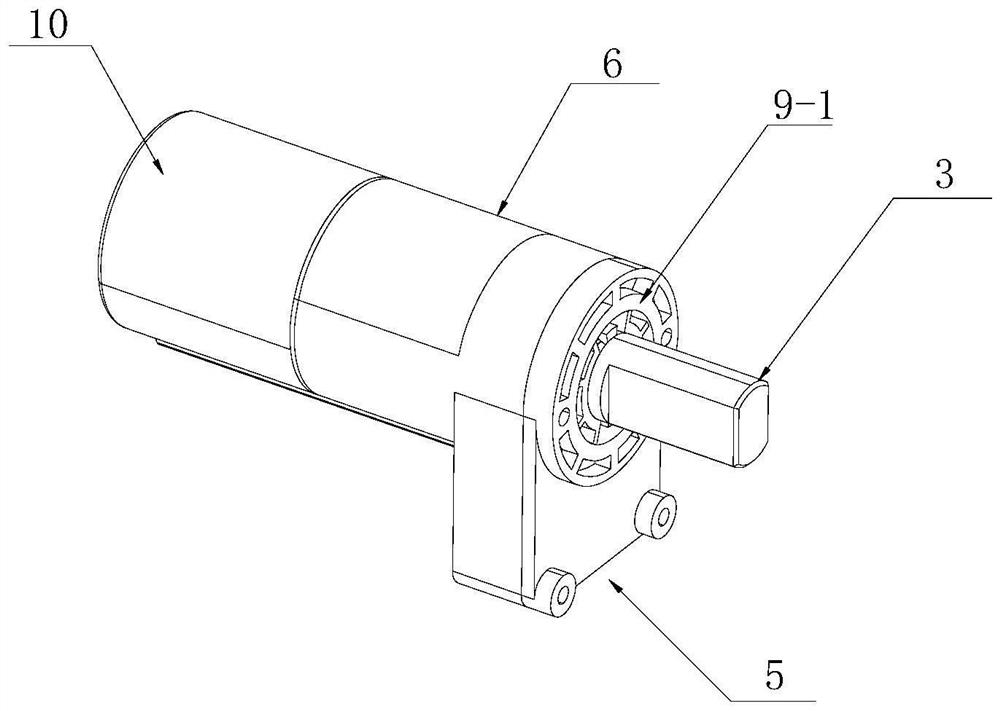
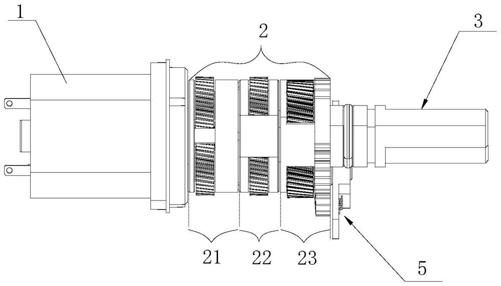
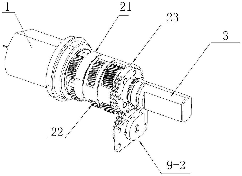
[0045] see Figure 1 to Figure 4 , an electric drive three-stage planetary deceleration driver, comprising a drive motor 1, a planetary deceleration mechanism installed in a ring gear housing 6, a power output shaft 3 and a motor output flange 4, the power shaft of the drive motor is mounted with a The first-stage sun gear 11; the first-stage sun gear is connected to the planetary deceleration mechanism 2; the planetary deceleration mechanism includes a first-stage planetary deceleration unit 21, a second-stage planetary deceleration unit 22 and a third-stage planetary deceleration unit 23, and also includes a power detection An angle detection device 5 for the rotation angle of the output shaft;
[0046] see Figure 5 to Figure 7 , the first-level planetary reduction unit 21 includes a first-level planet carrier assembly 211, a first-level planetary gear 218 installed in the first-level planetary carrier assembly; wherein the first-level planetary carrier assembly includes a first-level slewing support plate 212, a first-level planetary carrier assembly The planetary wheel disk 213, the first-level planetary shaft 214 arranged on the first-level planetary wheel disk, the first-level planetary shaft 214 and the first-level planetary wheel disk are integrally formed; The first-stage planetary wheel disc 213, in actual production, the first-stage planetary shaft 214, the connecting column 215 and the first-stage planetary wheel disc 213 are integrally formed, preferably injection molding, compared with the prior art, to ensure that the first-stage planetary shaft and the connecting column are Support strength, while reducing the process and time of secondary assembly, ensure the concentricity of the primary slewing support disc and the primary planetary wheel disc, avoid the installation error of the primary planetary deceleration unit, and solve the accumulative installation error of the primary planetary deceleration. The first-level planetary gear installation space 216 is formed between the first-level slewing support plate and the first-level planetary wheel, and the first-level planetary wheel installation space in the first-level planetary wheel installation space A first-level planetary gear 217 is installed on the shaft 214; the first-level planetary gear 217 meshes with the first-level sun gear 11 and the inner teeth of the ring gear housing 6 at the same time, and a second-level sun gear 218 is arranged on the first-level planetary wheel disc; its work The principle is to drive the motor to rotate the electric primary sun gear, the primary sun gear drives the three planetary gears to rotate, and the three planetary gears rotate to mesh with the inner teeth of the ring gear housing 6, thereby driving the primary planetary disc to coordinate the secondary sun gear. Rotate, realize the first-level deceleration and transmit the power to the lower-level deceleration unit. The first-level planetary deceleration unit can be independently debugged and replaced, which improves the assembly efficiency and ensures the qualified rate of the assembled products.
[0047] An overload protection device 7 is installed on the first-stage planetary reduction unit. The overload protection device includes an overload protection disc 7-0, a circular groove 2130 is provided on the first-stage planetary wheel disc 213 facing the secondary planetary reduction unit side, and an overload protection disc 7-0 is installed in the groove. 0, the overload protection disk is integrally provided with a central shaft 7-1, and the central shaft is provided with a secondary sun gear 219, and the overload protection is realized by the overload protection disk. The outer circumference has a convex rib 7-2 along the circumferential direction, and the inner wall of the circular groove of the secondary planetary wheel is evenly distributed with a limit groove 2131 that cooperates with the convex rib. Transmission torque, when the output end is overloaded, the ridges will move one by one along the limit groove, thereby achieving the purpose of overload protection of the drive motor.
[0048] An overload protection cover 8 is embedded on the outer side of the overload protection plate; a positioning groove 8-1 is arranged around the overload protection cover, and a positioning block 2132 is arranged on the overload protection plate corresponding to the groove. In production, it meets the requirements of lightweight design. The first-level planet carrier components are all plastic components, and the positioning block can be used to fix the overload protection gland by hot melting, but it is not limited to this. The overload protection gland can also be made of adhesive. Bonded to the overload protection disc.
[0049] see Figure 8 to Figure 13; The secondary planetary deceleration unit 22 includes a secondary planetary carrier assembly 221, and a secondary planetary wheel 222 installed in the secondary planetary carrier assembly; wherein the secondary planetary carrier assembly 221 includes a secondary slewing support plate 223, The secondary planetary wheel disc 224 and the secondary planetary shaft 225 integrally arranged on the secondary slewing support disc adopt an integrated design structure to ensure the accuracy of the installation position of the secondary planetary wheel; the other end of the secondary planetary shaft is fixedly connected to the secondary The planetary wheel, the second-level planetary wheel is integrally provided with a second-level planetary wheel accommodating cylinder 226, the second-level planetary wheel accommodating cylinder is provided with a second-level planetary wheel installation groove 227, and the second-level planetary shaft 225 is located in the second-level planetary wheel. In the accommodating cylinder, the secondary planetary gear 222 is installed on the secondary planetary shaft at the position of the secondary planetary gear installation groove; the secondary planetary gear meshes with the secondary sun gear 219 and the inner teeth of the ring gear housing at the same time; The center of the secondary planetary wheel disk on the side is provided with a third-stage sun gear 228; after the assembly is completed, the secondary planetary gear of the above-mentioned secondary planetary deceleration unit meshes with the secondary sun gear, and meshes with the inner teeth of the ring gear housing to realize power transmission. The second-stage deceleration drives the third-stage sun gear to rotate, and transmits the power to the lower-stage deceleration unit. The present invention adopts the above technical scheme, the present invention can realize the independent assembly of the secondary deceleration unit, and then assemble the driver as a whole, so as to improve the assembly efficiency, and the secondary planetary deceleration unit can be independently replaced and debugged, which greatly improves the qualification rate of the product; The position between remains relatively precise,
[0050] Preferably, a groove 226-1 is provided on the end surface of the secondary planetary wheel accommodating cylinder on the side of the secondary slewing support disk, and the depth of the groove is equal to the thickness of the secondary slewing support disk. The secondary slewing support plate is located in the groove, reducing the overall length of the assembled reducer.
[0051] Preferably, three dynamic balance adjustment holes 226-2 are provided along the circumferential direction on the end face of the second-stage planetary wheel accommodating cylinder on the side of the second-stage slewing support plate. The accommodating cylinder is concentric, and the debugging of the operation stability of the secondary planetary reduction unit can be adjusted through the dynamic balance debugging hole. When the dynamic balance of the secondary planetary reduction unit can be tested before assembly, the dynamic balance debugging hole can be filled with glue when adjustment is required. Liquid and other fillers can be used for adjustment; in addition, the dynamic balance debugging hole can also reduce the overall weight and meet the requirements of lightweight design.
[0052] Preferably, the diameter of the index circle where the dynamic balance debugging hole is located is greater than or equal to the outer diameter where the groove is located, which facilitates direct addition of fillers after assembly, and does not need to be disassembled for installation.
[0053] Preferably, the dynamic balance debugging hole is a blind hole to prevent the filler from falling, and to ensure that the secondary planetary deceleration unit is stuck due to the falling of the filler.
[0054] see Figure 14 to Figure 24 , the three-stage planetary reduction unit 23 includes a three-stage planetary carrier assembly 231, a three-stage planetary gear 232 installed in the three-stage planetary carrier assembly; wherein the three-stage planetary carrier assembly includes a three-stage slewing support plate 233 and an angle detection Gear plate 234, a three-stage planetary gear shaft 235 is installed between the three-stage slewing support plate and the angle detection gear plate, and a three-stage planetary gear 235 meshing with the third-stage sun gear 228 is installed on the three-stage planetary gear shaft; The three-stage slewing support plate 23 on the motor side is integrally provided with a three-stage planetary wheel accommodating sleeve 236, which adopts an integrated structure, on the one hand, reduces the number of parts, and the main purpose is to accommodate the three-stage slewing support plate 23 and the third-stage planetary gear. The position of the sleeve 236 is relatively fixed, thereby ensuring the positional accuracy of the third-stage planetary wheel installed in it, and at the same time, it has the effect of sound absorption; the side wall of the third-stage planetary wheel accommodating sleeve is provided with a gap 237, and the third-stage planetary wheel extends out of the gap Mesh with the inner teeth of the ring gear housing; install the angle detection toothed plate connecting column 238 on the end face of the support wall of the third-stage planetary gear accommodating sleeve adjacent to the gap; the angle detection toothed plate connecting column is connected to the angle detection toothed plate 234; the angle detection The gear plate is connected to the power output shaft 3 .
[0055] Preferably, the three-stage slewing support plate is provided with a weight reduction hole 238-1 extending in the direction of the connection column of the angle detection chainring corresponding to the position of the connecting column of the angle detecting chainring. Design requirements, and also has the function of vacuuming noise.
[0056] Preferably, a positioning boss 233-1 is provided on the end face of the three-stage slewing support plate to ensure the interval with the two-stage deceleration planetary unit, reduce friction, eliminate the need for independent gasket structure design, and improve assembly efficiency.
[0057] Preferably, the angle detection chainring and the power output shaft are integrated into a composite structure, that is, the angle detection chainring body and the power output shaft body are integrally made of metal materials. The outside is wrapped with an engineering plastic layer. This structure first reduces one step of assembly process in the assembly process, and the strength of the power output shaft is higher than that of the split body. In addition, due to the different types of products applied to the product of this application, the body can be universal, and production can be reduced. cost; in addition, the angle detection gear plate and the power output shaft of the present invention can also adopt a separate structure.
[0058] The angle detection device 5 includes an angle detection box 9 arranged on the side of the casing close to the power output shaft end, and a flange box cover 9-1 is installed on the angle detection box on the side away from the drive motor. The output shaft extends out of the flange cover, and the angle detection element 9-2 for detecting the rotation angle of the power output shaft is installed in the angle detection box. The inner teeth of the body realize the three-stage deceleration of power, and drive the angle detection tooth plate to rotate, transmit the power to the power output shaft 3, and output the power, and at the same time drive the angle detection tooth plate to rotate within the set angle range.
[0059] The angle detection element adopts a gear potentiometer, the gear potentiometer is installed on the potentiometer installation shaft 9-3 in the angle detection box, and the potentiometer gear 9-4 of the gear potentiometer meshes with the angle detection tooth plate 234 ; An angle sensor drive shaft 9-5 is coaxially arranged on the potential gear, and the angle sensor drive shaft is connected to the angle sensor 9-6. The rotation angle of the power output shaft is detected and fed back in real time through the gear potentiometer, so as to reflect the opening degree of the actuator installed with the driver of the present invention.
[0060]The cross section of the angle sensor drive shaft is a D-shaped structure, the angle sensor drive shaft is provided with a groove 9-7 open to the plane side of the D-shaped structure along the axial direction, and an elastic sheet 9-7 is provided at the opening position of the groove. 8. When the shrapnel is pressed, the shrapnel will deform inwardly, thereby realizing the installation of the potential gear and preventing it from falling off during the assembly process.
[0061] Preferably, the end of the elastic sheet is provided with an inclined guide surface to guide the installation of the drive shaft of the assembled guide angle sensor to improve installation efficiency.
[0062] Preferably, limit pins 9-9 are provided on the angle detection toothed plate on the side of the flange box cover, and arc limit grooves 9-10 are arranged on the inner side of the flange box cover corresponding to the position of the limit pins. This structure is adopted. During the rotation process, the limit pins 9-9 on the angle detection gear plate move in the arc limit slot, and the arc limit slot is a two-way through slot, which can realize left and right interchange, which solves the problem of the existing technology, the single left and right single The arc-shaped limit slot is independently set on the side, resulting in asymmetric left and right, and it is necessary to produce left and right flange box covers; but with this technical solution, only one flange box cover is needed to meet the installation requirements of the left and right stations. , in actual installation, it is only necessary to adjust the initial position of the limit pin relative to the arc limit groove, thereby reducing the production cost and making the flange box cover universal.
[0063] Preferably, at least one elastic claw 9-10 is provided on the outer circumference of the mounting hole of the power output shaft of the flange case cover, and a limit slot 3-1 is provided on the power output shaft. When the traditional power take-off shaft is installed, the circlip is used to limit the position. This technical solution replaces the existing circlip, saves a circlip assembly link, improves production efficiency and product stability, and reduces production costs.
[0064] Further, a motor flange is installed on the power shaft end of the driving motor, and a motor sealing cover 10 is sleeved on the motor flange, which protects the driving motor and prolongs the service life of the driver in industrial and mining conditions such as humidity and dust.
[0065] To sum up, on the basis of ensuring the original deceleration and power output, the present invention can realize independent assembly of the three-stage deceleration unit, and then assemble the driver as a whole, and each stage of the planetary deceleration unit can be independently replaced and debugged, which greatly improves the product quality. Pass rate.
[0066] The above descriptions are only preferred embodiments of the present invention, and are not intended to limit the present invention. Any modifications, equivalent replacements and improvements made within the spirit and principles of the present invention, such as materials, dimensions, elastic pieces and grooves The number of coordination should be included within the protection scope of the present invention.

PUM

no PUM

Description & Claims & Application Information

We can also present the details of the Description, Claims and Application information to help users get a comprehensive understanding of the technical details of the patent, such as background art, summary of invention, brief description of drawings, description of embodiments, and other original content. On the other hand, users can also determine the specific scope of protection of the technology through the list of claims; as well as understand the changes in the life cycle of the technology with the presentation of the patent timeline. Login to view more.

Similar technology patents

Extensible collector ring

Owner:杭州摇头龙科技有限公司

Automatic screw assembling machine

InactiveCN106624756AImprove assembly efficiencyshorten delivery time
Owner:CHANGSHA RUIBOTE TECHNOLGOY CO LTD

Automatic detecting device

Owner:KUNSHAN HAIWEI AUTOMATION

Automatic thread binding equipment for paper

ActiveCN106985567AImprove assembly efficiencyrealize positioning
Owner:庸博(厦门)电气技术有限公司 +3

Method and system for in-situ coating of electrospinning nanofiber film on surface of material

InactiveCN109972292ALower assembly costsImprove assembly efficiency
Owner:中国科学院苏州纳米技术与纳米仿生研究所南昌研究院

Classification and recommendation of technical efficacy words

  • Improve pass rate
  • Improve assembly efficiency

Preparation method of high-tensile high-model heterocycle aramid fiber

ActiveCN101787582ALess fuzz on the surfaceImprove pass rate
Owner:CHINA BLUESTAR CHENGRAND CO LTD

Quantitative reverse deformation arrangement based method for designing cast model

ActiveCN101767185AImprove pass rateReduce the number of calculation iterations
Owner:INST OF METAL RESEARCH - CHINESE ACAD OF SCI +1

Electric wheelbarrow structure

InactiveCN103407529AImprove assembly efficiencyEase of daily maintenance and disassembly for repairs
Owner:CHANGZHOU AIRWHEEL INTELLIGENT TECH

Assembling device for luminous wheel product

InactiveCN107052791Aimprove assembly efficiencyGuaranteed assembly quality
Owner:浙江美佳尼精密科技有限公司

Automatic assembling device of fog lamp dimming ball component

ActiveCN103386609AReduce auxiliary operation timeImprove assembly efficiency
Owner:CHANGZHOU XINGYU AUTOMOTIVE LIGHTING SYST
Why Eureka
Try Eureka