Electroplating clamp and assembly line capable of realizing vertical rack plating and horizontal rotary electroplating

An electroplating fixture and assembly line technology, applied in the direction of electrolytic components, electrolytic process, cells, etc., can solve the problems of electroplating solution leakage, pollution of cathode contact substrate area, poor sealing of electroplating fixture, etc., to maintain stability, improve electroplating effect, The effect of improving work efficiency

Pending Publication Date: 2022-05-31
XIAMEN UNIV
View PDF0 Cites 1 Cited by
  • Summary
  • Abstract
  • Description
  • Claims
  • Application Information

AI Technical Summary

Problems solved by technology

[0003] The purpose of this application is to provide an electroplating fixture and an assembly line capable of vertical rack plating and horizontal rotary electroplating, in order to solve the problem of poor sealing of the electroplating fixture, causing leakage of the electroplating solution, polluting the cathode contact and the substrate area that does not need electroplating

Method used


Image

  • Electroplating clamp and assembly line capable of realizing vertical rack plating and horizontal rotary electroplating
  • Electroplating clamp and assembly line capable of realizing vertical rack plating and horizontal rotary electroplating
  • Electroplating clamp and assembly line capable of realizing vertical rack plating and horizontal rotary electroplating

Examples


Embodiment 1

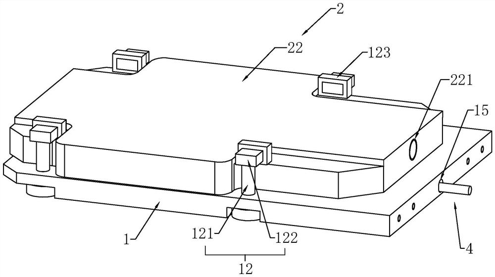
[0051] refer to figure 1 , an electroplating fixture, including a support plate 1 and a seal 2 .

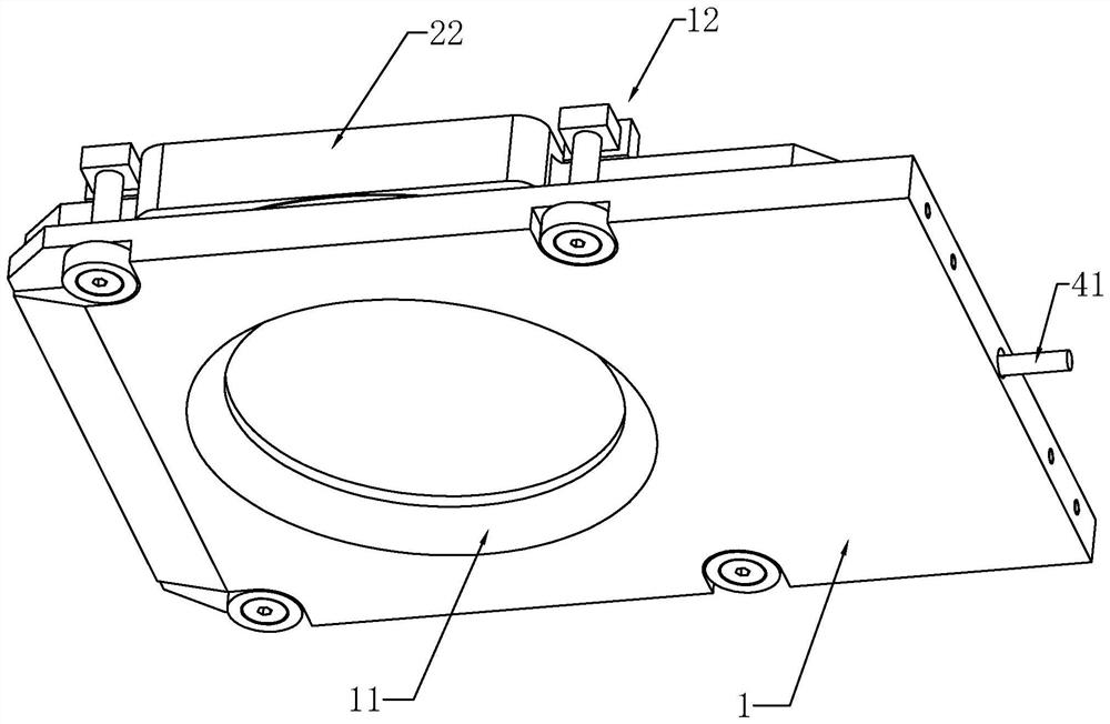
[0052] refer to figure 1 and figure 2 , the support plate 1 is provided with a cavity 11 along its thickness direction. The cavity 11 has a flared structure. When installing the base plate 3, the base plate 3 is placed on the support plate 1, and the side with the smaller diameter of the cavity 11 is shielded. The support plate 1 is also mounted with a conductive component 4 for contacting and conducting electricity with the substrate 3 .

[0053] refer to image 3 and Figure 4 , the sealing member 2 includes a sealing plate 21 and a driving member. The sealing plate 21 has a disc structure as a whole. The sealing plate 21 is used to shield the side of the substrate 3 away from the support plate 1 . Since the substrate 3 is usually thin, a buffer pad 211 is embedded and fixed on the side of the sealing plate 21 close to the support plate 1 , and the buffer pad 211 can ...

Embodiment 2

[0070] refer to Figure 13 and Figure 14 , and the difference from the first embodiment is that the first annular groove 13 is opened on a side wall of the sealing plate 21 close to the supporting plate 1 . The first sealing ring 5 is embedded and fixed in the first annular groove 13 . The height of the outer peripheral groove wall of the first annular groove 13 is higher than that of the inner peripheral groove wall.

Embodiment 3

[0072] refer to Figure 15 The difference from the first embodiment is that the conductive ring 42 is an integral annular structure, the conductive ring 42 and the elastic contact piece 43 are integrally connected, and the conductive ring 42 and the conductive rod 41 can be fixed by welding. One end of the elastic contact piece 43 is connected to the inner wall of the conductive ring 42 , the other end is arched toward the sealing plate 21 and then extends away from the sealing plate 21 , and the end extends axially along the conductive ring 42 as a whole. The elastic contact piece 43 has a curved strip-like structure as a whole.


PUM


Abstract

The invention discloses an electroplating clamp and an assembly line capable of achieving vertical rack plating and horizontal rotary electroplating, and relates to the technical field of electroplating clamps. A cavity is formed in the supporting plate in the thickness direction; the substrate is placed on the supporting plate and shields one side edge of the cavity; a conductive assembly used for being in contact with the substrate for electric conduction is installed on the supporting plate. The sealing piece comprises a sealing plate for shielding the substrate and a driving piece for driving the sealing plate to be close to or away from the supporting plate; a first sealing ring and a second sealing ring are arranged between the supporting plate and the sealing piece. When the sealing plate abuts against the supporting plate, the first sealing ring is clamped between the supporting plate and the sealing plate, and the first sealing ring surrounds the periphery of the base plate. The second sealing ring is clamped between the supporting plate and the base plate, and the second sealing ring is located on the inner side of the base plate. The sealing of the non-electroplating area of the substrate can be improved, and the electroplating quality is improved.

Description

technical field [0001] The present application relates to the technical field of electroplating equipment, in particular to electroplating fixtures and assembly lines capable of vertical rack plating and horizontal rotary electroplating. Background technique [0002] In the field of semiconductor manufacturing, electroplating is a common method for depositing thin metal films on substrates. Especially in the field of advanced packaging, since electroplating has the advantages of simple process, low cost, and various deposited metals, electroplating is generally used to fill and deposit metals on the substrate to realize circuit interconnection. Electroplating fixture is an important part of the electroplating process, and a good electroplating fixture can greatly improve the quality of electroplating. There are more or less various problems in the current electroplating fixtures on the market, which greatly hinder the electroplating effect. When the electroplating fixture ...

Claims


Application Information

Patent Timeline
Patent Type & Authority Applications(China)
IPC IPC(8): C25D17/06C25D19/00C25D17/00C25D21/00
CPCC25D17/06C25D17/00C25D17/004C25D17/005C25D21/00
Inventor 马盛林王其强
Owner XIAMEN UNIV
Why Eureka
Try Eureka