

Leakage groove air film cooling structure used for turbine end wall and provided with protrusions and application of leakage groove air film cooling structure
A technology of air film cooling and leakage grooves, applied in the direction of climate sustainability, blade support elements, sustainable transportation, etc., can solve the problem of reduced cooling efficiency in the end wall area of the pressure side, cooling protection in the area between holes, and turbine end wall Unfavorable thermal protection and other issues, to achieve the effect of increasing coverage, weakening supercooling coverage, and high uniformity of cold air jet
- Summary
- Abstract
- Description
- Claims
- Application Information
AI Technical Summary
Problems solved by technology
Method used
Image

Examples
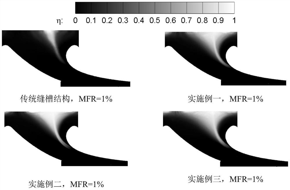
Embodiment 1
[0045] In this embodiment, a film cooling structure for leakage grooves with protrusions on the end wall of the turbine, the chord length of the protrusion structure 2 on the inner wall of the leakage groove is 1 / 4H 1 . Inside the leakage groove structure 1 upstream of the turbine cooling wall surface 3, 0.6W is arranged along the height direction of the leakage groove 1 The width of the ring-shaped protrusion 2, and the leakage groove air supply chamber 5. Protruding structures 2 are arranged inside the leakage groove structure 1, and the convex structures 2 are arranged periodically along the suction surface and the pressure surface, and the cold air jet flow direction of the leakage groove is perpendicular to the surface of the end wall.
[0046] Leakage groove structure 1 corresponds to the spanwise length H of one cascade period 1 46mm, width W 1 It is 2.48mm, and the cold air flow direction is perpendicular to the main flow.
[0047] The protruding structure 2 is an ...
Embodiment 2
[0051] In this embodiment, a film cooling structure for leakage grooves with protrusions on the end wall of the turbine, the chord length of the protrusion structure 2 on the inner wall of the leakage groove is 3 / 8H 1 . Inside the leakage groove structure 1 upstream of the cooling end wall 3 of the turbine, a 0.5W 1 The width of the ring-shaped protrusion 2, and the leakage groove air supply chamber 5. Protruding structures 2 are arranged inside the leakage groove structure 1, and the convex structures 2 are arranged periodically along the suction surface and the pressure surface, and the cold air jet flow direction of the leakage groove is perpendicular to the surface of the end wall.
[0052] Leakage groove structure 1 corresponds to the spanwise length H of one cascade period 1 46mm, width W 1 It is 2.54mm, and the cold air flow direction is perpendicular to the main flow.
[0053] The protruding structure 2 is an arc structure with a chord length of H 2 , its value is...
Embodiment 3
[0057] In this embodiment, a film cooling structure for leakage grooves with protrusions on the end wall of the turbine, the chord length of the protrusion structure 2 on the inner wall of the leakage groove is 1 / 2H 1 . Inside the leakage groove structure 1 upstream of the cooling end wall 3 of the turbine, a 0.4W 1 The width of the ring-shaped protrusion 2, and the leakage groove air supply chamber 5. Protruding structures 2 are arranged inside the leakage groove structure 1, and the convex structures 2 are arranged periodically along the suction surface and the pressure surface, and the cold air jet flow direction of the leakage groove is perpendicular to the surface of the end wall.
[0058] Leakage groove structure 1 corresponds to the spanwise length H of one cascade period 1 46mm, width W 1 It is 2.61mm, and the cold air flow direction is perpendicular to the main flow.
[0059] The protruding structure 2 is an arc structure with a chord length of H 2 , whose value ...
PUM
| Property | Measurement | Unit |
|---|---|---|
| Width | aaaaa | aaaaa |
| Length | aaaaa | aaaaa |
| Width | aaaaa | aaaaa |
Abstract
Description
Claims
Application Information