[0038] Example 1
[0039] In an exemplary embodiment of the present invention, as Figure 1-Figure 4 As shown, a motion control method for quadruped robot based on reinforcement learning and position increment is presented.
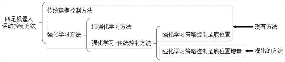
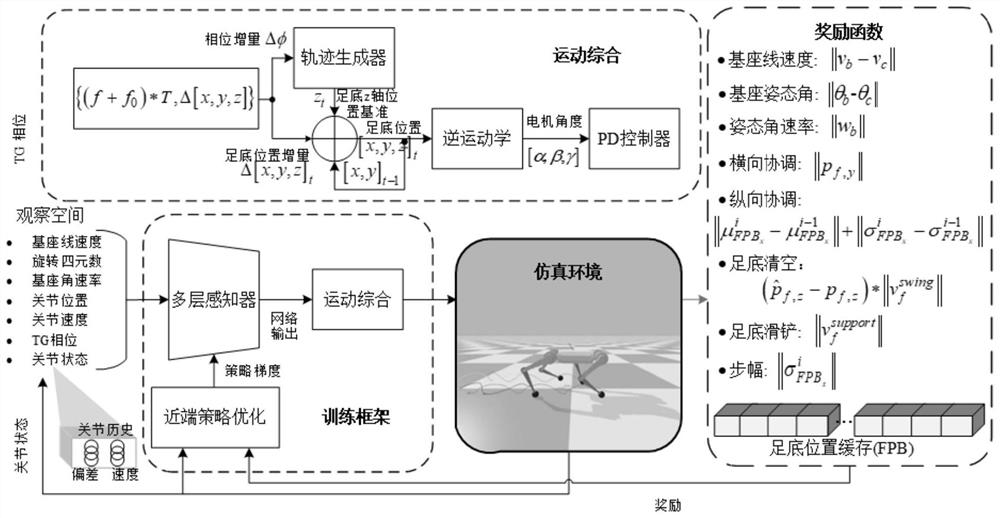
[0040] like figure 1 As shown, different from the existing gait control methods of quadruped robots, this embodiment proposes a quadruped robot motion control method based on reinforcement learning and position increment, which allows the quadruped robot to learn the sole of each time step. The amount of change in position, avoiding abrupt changes in control commands, enables the quadruped robot to learn smooth and coordinated movements within the RL framework and reduces the difficulty of hyperparameter tuning during the training phase. Reinforcement learning needs to interact with the environment to learn, and the trial-and-error and randomness of the strategy in the early stage of training is likely to cause irreversible damage and damage to the robot, making it impossible to train in the real environment. Therefore, this scheme realizes the autonomous motion of the quadruped robot by training in the simulation environment and then migrating to the real environment.
[0041] For the quadruped robot motion control method based on reinforcement learning and position increment, such as figure 2 It mainly includes the following steps:
[0042] Obtain motion environment information, quadruped robot posture information and sole position information;
[0043] Based on the obtained information, generate the position of the sole of the foot in each preset time step when the quadruped robot moves, and calculate the variation of the position of the sole of the foot in each time step;
[0044] Constrained by the maximum moving distance in a single time step, and accumulating time steps to obtain the foot position trajectory;
[0045]The quadruped robot is controlled to perform corresponding actions based on the foot position trajectory combined with the preset reward function, so as to keep the quadruped robot in motion balance.
[0046] Specifically, considering the motion problem of a quadruped robot, we regard the motion problem of a quadruped robot as a partially observable Markov decision process (POMDP) < S, A, R, P, γ >, where S and A are respectively Represents state and action space. R(s t ,s t+1 )→R is the reward function, P(s t+1 ∣s t ,a t ) is the transition probability and γ∈(0,1) is the reward discount coefficient. The quadruped robot takes an action a in the current state, obtains a scalar reward r, and then transitions to the next state s, determined by the state transition probability distribution P(s t+1 ∣s t ,a t ). The overall goal of quadruped robot training is to find an optimal policy Maximize future discounted rewards, namely:
[0047]
[0048] combine figure 2 The shown quadruped robot gait training framework mainly includes three parts: the design of the observation space, the design of the action space and the design of the reward function. Reinforcement learning uses the designed reward function to guide the robot to continuously explore in the physical simulation environment to adapt to the complex environment, and finally learn to obtain a robust motion controller. The Proximal Policy Optimization (PPO) algorithm and the set reward function are used to optimize the RL strategy. The input is simply preprocessed sensor data, and the output is the incremental plantar position proposed in this scheme, which is finally converted into motor position control. instruction. In addition, the quadruped robot can track upper-level user commands, including the forward speed of the base and yaw angle Speed command vector v c and the rotation direction command vector θ c are defined as and During the training phase, the quadruped robot is encouraged to obey upper-level user commands, maintain balance and complete coordinated movements.
[0049] observation space design
[0050] In this embodiment, the quadruped robot only contains the most basic proprioceptive sensors, including an inertial measurement unit (IMU) and 12 motor encoders, which can measure the reference linear velocity v of the body b ∈R 3 , the direction θ b ∈R 3 or its quaternion form q b =[x,y,z,w]∈R 4 , angular velocity w b ∈R 3 and joint position θ j ∈R 12. joint speed It can be estimated by the extended Kalman filter. Due to the lack of plantar pressure sensors, this scheme introduces the joint state history Θ as the network input to realize ground contact detection, where Θ includes joint position error and joint velocity, etc. Among them, the joint position error is defined as the deviation between the current joint position and the joint position command at the previous moment. In addition, the leg phase φ is also used as the network input, which is uniquely represented by. Therefore, the entirety of the state space at time t is defined as These states are preprocessed and normalized as the input of the network, and then the action commands at the next moment are generated to control the motion of the quadruped robot, and the cycle continues.
[0051] action space design
[0052] At present, the commonly used gait learning methods of quadruped robots are mainly based on direct output of motor position or plantar position command, which may cause the position command to change abruptly between two short continuous time steps, resulting in excessive joint generation. Torque to track the target position, causing motor damage. In response to this problem, this scheme proposes a gait learning method based on incremental plantar position, which allows the quadruped robot to learn the variation of the plantar position at each time step, avoids sudden changes in control commands, and achieves smooth and smooth gait trajectory. The schematic diagram of the developmental model of incremental gait learning is as follows image 3 , area II is the plantar position area that can be selected by the reinforcement learning strategy, and area III is the allowable plantar change position range under the incremental gait.
[0053] This new incremental action space explicitly constrains the maximum movement distance of the foot in a single time step, while accumulating time steps to obtain the optimal plantar position trajectory. As the plantar trajectory moves, the plantar position space changes dynamically until the mechanical limit is reached, such as image 3 Area I in . This approach enables reinforcement learning policies to be optimized directly with rewards related to the primary task (e.g. learning a tetrapod-like gait) without considering the negative effects of penalizing sudden changes in the motor state in the reward function, as might lead to motor jitter or static state, etc.
[0054] In order to make the quadruped robot learn a natural and regular gait, Policies Modulating Trajectory Generators (PMTG) are introduced to assist the quadruped robot in training. Each leg uses an independent trajectory generator (TG) to output the plantar position in the g-axis direction. TG is defined as Cubic Hermite Spline to simulate the basic stomping gait pattern, the formula is as follows:
[0055]
[0056] In the formula, k=2(φ-π)/π, h is the maximum allowable foot lift height, and φ∈[0, 2π) is the TG phase. Among them, the supporting phase is φ∈[0, π), and the wobbling phase is φ∈[π, 2π).
[0057] The reinforcement learning strategy outputs the position delta Δ[x, y, z] of the sole of the foot and the frequency of accommodation f for each leg. The phase of the i-th leg can be determined by the formula φ i =(φ i,0 +(f 0 +f i )*T)(mod 2π) calculation. where φ i,0 is the initial phase of the i-th leg, f 0 is the fundamental frequency, and T is the time between two consecutive control steps. The target plantar position (x, y, z) t at time t can be obtained by the following formula:
[0058] (x, y, z) t =Δ(x, y, z) t +(x t-1 , y t-1 , F(φ t )) (3)
[0059] It can be seen from the above formula that the plantar position along the x and y axes can be obtained by accumulating the plantar position increments (Δx, Δy) output by the network, and the foot position along the z axis is obtained by the plantar position increment Δz output by the network. It is superimposed with the prior value provided by TG. The former makes the target position of the foot change more smoothly, while the latter makes it easy to obtain regular periodic motion. The position of the target sole is pre-defined in the robot basic framework, and then the corresponding target motor position is calculated by inverse kinematics (IK), and finally the joint torque is calculated by the proportional derivative (PD) controller to track the target motor position.
[0060] reward function design
[0061] The design of the reward function is the key to the entire reinforcement learning framework, and it plays two roles at the same time. One is ability evaluation, where human designers use a specified reward function to evaluate the behavior of quadruped robots; the other is behavioral guidance, where the implementation of RL algorithms uses the reward function to determine the behavior of the robot. The mathematical form and design goal of the reward function designed in this subject will be described in detail below. First, the following two kernel functions are introduced to constrain the reward function to ensure that the reward value is within a reasonable range:
[0062]
[0063]
[0064] Designing Robot Base Linear Velocity Rewards and spin direction bonus to encourage the robot to follow a given velocity command v c and the rotation direction command θ c , the specific form is as follows:
[0065]
[0066] where v b and θ c are the base linear velocity and rotation direction, respectively, the velocity norm ||v c || The reward can be scaled to an appropriate range.
[0067] Design Angular Velocity Bonus Encourage the robot to keep the base stable without shaking:
[0068] Designing Lateral Coordination Rewards to minimize the lateral offset of each leg, as in Figure 4 shown.
[0069]
[0070] in the formula is the component of the plantar position of the i-th leg on the y-axis.
[0071] Designing Vertical Alignment Rewards Encourage the same stride on all four legs and minimize the longitudinal offset (sagittaloffset), as in Figure 4 shown.
[0072]
[0073] in, and are the mean and standard deviation of the x-axis components along the plantar position of the i-th leg in the past time steps, respectively. Lateral coordination reward and vertical coordination rewards The synergy enables the robot to learn to develop a coordinated, natural gait.
[0074] Design stride reward Robots are encouraged to prioritize increasing/decreasing stride length over motion frequency when increasing/decelerating speed, defined as:
[0075]
[0076] Designing a side slip reward Penalize the sliding of the foot during the support phase, defined as:
[0077]
[0078] Designing a Plantar Raise Reward The foot is allowed to move at a higher height during the swing phase, defined as:
[0079]
[0080] All the above reward functions work together to guide the quadruped robot to complete the learning process of gait autonomous learning and development, and finally the reward r at each time step t t for:
[0081]
[0082] where k c,tis the course factor. The curriculum factor is an adjustment parameter introduced by curriculum learning to describe the difficulty of training.
[0083] As an effective deep reinforcement learning training algorithm, curriculum learning is often introduced into the training of agents. The core idea is to start learning from a simple task or a part of the task, and then gradually increase the difficulty of the task, so that the agent finally learns the entire complex task.
[0084] Based on this, the method of curriculum learning is introduced in this embodiment, so that the robot learns the main tasks (obeying motion commands and maintaining body balance) preferentially at the beginning of the training phase, and then gradually increases the coefficient of the constraint term. course factor k c,t describes the level of difficulty during training, defined as where k d means k c,t The rate of increase to reach the maximum course difficulty level. The PPO hyperparameter settings are shown in Table 1.
[0085] Table 1PPO hyperparameter settings
[0086]